‐29‐
MAIN COMMUNICATION UNIT (MCU) [MPX 100 CBC]
The Main Communication Unit (MCU) monitors the modules and units inserted within the Modular UPS Power Cabinet and also
all the other Cabinets within the system. The MCU is equipped with a 7” colour touch screen display which shows in an easy an
intuitive way all of the electrical values and the system status. It also enables the user to control and configure the system as
required. The MCU also houses the communication ports for remote monitoring by the user and authorised personnel. For more
information please refer to the chapter on the display and the chapter “Remote Communication and accessories”.
INSERTION/EXTRACTION PROCEDURE
The following operations must only be performed by skilled and specifically trained personnel.
When the MCU is not inserted, uncovered parts with dangerous voltage are present on the corresponding
backplane.
The MCU is pre-installed by the manufacturer. Remove the MCU only in case of maintenance or replacement.
Strictly comply with the instructions as listed below.
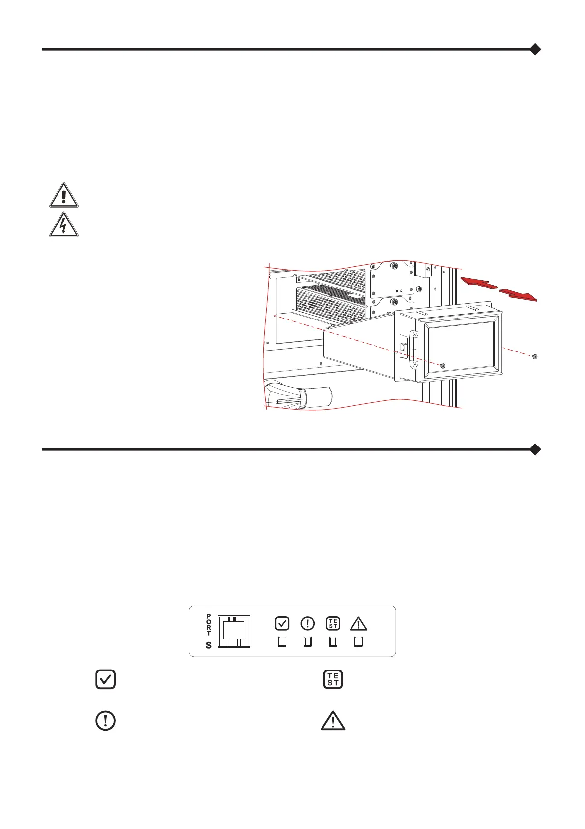
EXTRACTION
Undo the two side screws.
Using the dedicated handles on the sides of the
display, carefully pull and remove the MCU.
INSERTION
Carefully insert the MCU in the dedicated slot.
Fasten the MCU by fastening the two side screws
removed previously.
CONNECTIVITY PANEL (CP) [MPX 130 PWC]
The Connectivity Panel (CP) integrates the logic functions of the MCUs and MUs (that are contained within other types of
Cabinets). Therefore, it carries out the monitoring of the units and modules contained within the Modular UPS Power Cabinet and
of all other Cabinets within the system. It monitors the status of the internal and external disconnection switches, the status of the
Power Supply Units and the internal and external temperatures. The CP is equipped with a 7” colour touch screen display which
shows in an easy an intuitive way all the electrical values, the system status and enables the main commands, settings and
configurations. The CP also houses the communication ports for remote monitoring by the user and authorised personnel. For
more information please refer to the chapter on the display and the chapter “Remote Communication and accessories”.
INTERFACE PANEL
Green
On steady: MU ready
Green
Slow blinking: Test in progress
Yellow
On steady: Anomaly
Red
On steady: Alarm
PORT S
Communication port reserved for service personnel only