‐24‐
BYPASS MODULE (BM)
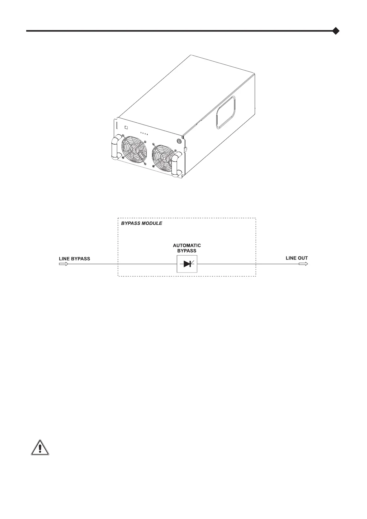
The Bypass Module (BM) allows the direct connection, electronically governed, between the input and the output of the Modular
UPS Cabinet. The wiring diagram of the BM, which shows its individual components, is provided below:
Bypass Module wiring diagram
BACKFEED PROTECTION
The BM continuously monitors the bypass line for backfeed protection, and if required, the system will remove any dangerous
voltage from the input terminals.
The type of action depends on the BM model installed within the system:
MPX 130 BM (BM126X)
If a BACKFEED is detected, the system transfers the output onto the automatic bypass and disconnects the inverter line (via
relays). The load is powered from the bypass line. If the protective action is triggered whilst on battery operating mode, the load
will be disconnected for safety reasons.
MPW 130 BM
If the BACKFEED is detected, the system disconnects the automatic bypass line (via contactor). The load remains powered by
the inverter even during battery operating mode.
Warning: to avoid any safety and/or malfunctioning issues, all the BMs within the same system must be of
the same model.