0ML190480RUENUC page12/24
REMOVE TRAYS
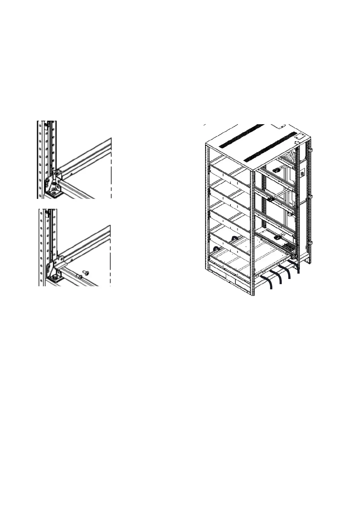
1. To facilitate the assembly operations, all the trays, except the number 1, can be removed and
assembled out of cabinet
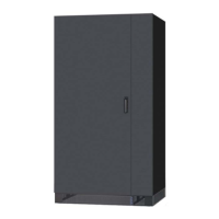
2. Remove the tray block, on both sides, remove the screws as shown in Fig. 5; on each block is
stamped the number referred to tray (see Fig. 4 for tray numbers)
3. Pull off the trays N. 2-3-4-5
Arrange n.4 straps (listed pos.14) as shown in Fig. 6. These will be used to ensure the battery
blocks once assembled.
POSITIONING AND INSTALLING BATTERIES
Use the components supplied inside the cabinet and listed in the previous section (position 1÷15) to assembly
the trays, following the procedure below. See the ” Table 3- torque values ” to connect busbars to batteries
blocks terminal and lugs to busbar terminal.
Tray n.1 must be assembled inside the cabinet
Trays n. 2-3-4-5: to facilitate the assembly, the operations can be performed out of the cabinet.The assembled
trays must be placed inside the cabinet using a forklift (Fig. 12)
The assembled trays must be placed in the cabinet proceeding from the lowest (tray n.2) to highest (tray n.5)
Fig.5‐screwsfortraybloc
Fig.6‐straps