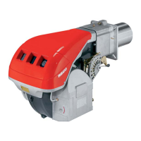
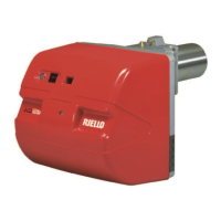
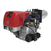
Technical description of the burner
15
20051011
Key Fig. 8:
Tab. H
Times
Tab. I
AL
Alarm device
AUX
Auxiliary output
Dbr
Wire link
Lockout reset button (info button)
EK2
Remote lockout reset button
FSV
Flame signal amplifier
ION
Ionization probe
K...
Relay contact
LED
3-color signal lamp
LP
Air pressure switch
LR
Load controller
LR-OPEN
Load controller OPEN position
LR-CLOSE
Load controller CLOSED position
M
Fan motor
NT
Power supply unit
P LT
Pressure switch valve proving
Pmax
Pressure switch-max
Pmin
Pressure switch-min
POC
Proof of closure
PV
Pilot valve
QRA...
UV flame detector
R
Control thermostat or pressurestat
SA
Actuator
SA-KL
Actuator low-fire
SA-NL
Actuator high-fire
SA-R
Actuator feedback
SA-Z
Actuator CLOSED
SA-ZL
Actuator ignition load
SL
Safety loop
STB
Safety limit thermostat
SV
Safety valve
V1
Fuel valve
V2
Fuel valve
V2a
Fuel valve
W
Limit thermostat or pressure switch
Z
Ignition transformer
µC µC controller
Input/output signal 1 (ON)
Input/output signal 2 (OFF)
Input permissible signal 1 (ON) or 0 (OFF)
TSA Safety time
tw Waiting time
t1 Prepurge time
t3 Preignition time
t3n Postignition time (P257 +0.3 seconds)
t4 Interval: end of safety time load controller
release
t5 Interval: Pilot valve OFF - load controller
release
t8 Postpurge time
t10 Specified time air pressure switch state mes-
sage (timeout)
t11 Opening time of actuator (timeout)
t12 Closing time of actuator (timeout)
td1 Test atmospheric pressure
td2 Test gas pressure
td3 Test space filling
td4 Test space evacuating






 To Next Page