20051011
38
Operation, indication, diagnostics
7.1 Control sequence in the event of fault
If lockout occurs, the outputs for the fuel valves, the burner motor
and the ignition equipment are immediately deactivated (<1 sec-
ond).
Tab. U
In the event of lockout, the LME71… remains locked and the red
fault signal lamp lights up. The burner control can immediately be
reset. This state is also maintained in the event of mains failure.
7.2 Fault status messages, display of errors
7.2.1 Display of errors (faults) with lockout
Tab. V
7 Operation, indication, diagnostics
Cause Response
Mains voltage failure Restart
Voltage below undervoltage threshold Safety shutdown
Voltage above undervoltage threshold Restart
Extraneous light before safety time Lockout
Extraneous light during waiting time Start prevention, lockout after approx. 30 seconds at the latest
No flame at the end of safety time Lockout end of safety time
Loss of flame during operation Factory setting: lockout
Can be parameterized: (depending on program module 1 x repeti-
tion
Air pressure switch has welded in the operating position Start prevention, lockout after 30 seconds
Air pressure switch has welded in the noload position Lockout at the end of the specified time
No air pressure signal on completion of the specified time Lockout, with breakdown time
0.3 seconds
POC contact is open during startup Lockout, approx. 5 seconds after temperature thermostat or pres-
surestat or temperature or pressure switch on
Pressure switch-min: failure during operation Shutdown and start prevention
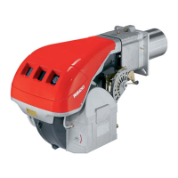
Display shows alternately Loc and 4.
Unit is in the lockout position.
The current error code is displayed and the signal lamp is blinking red.
Example: error code 4
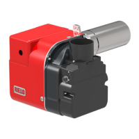
Press or for display of the phase, where the fault appeared.
Signal lamp blinks red.
Example: phase P02
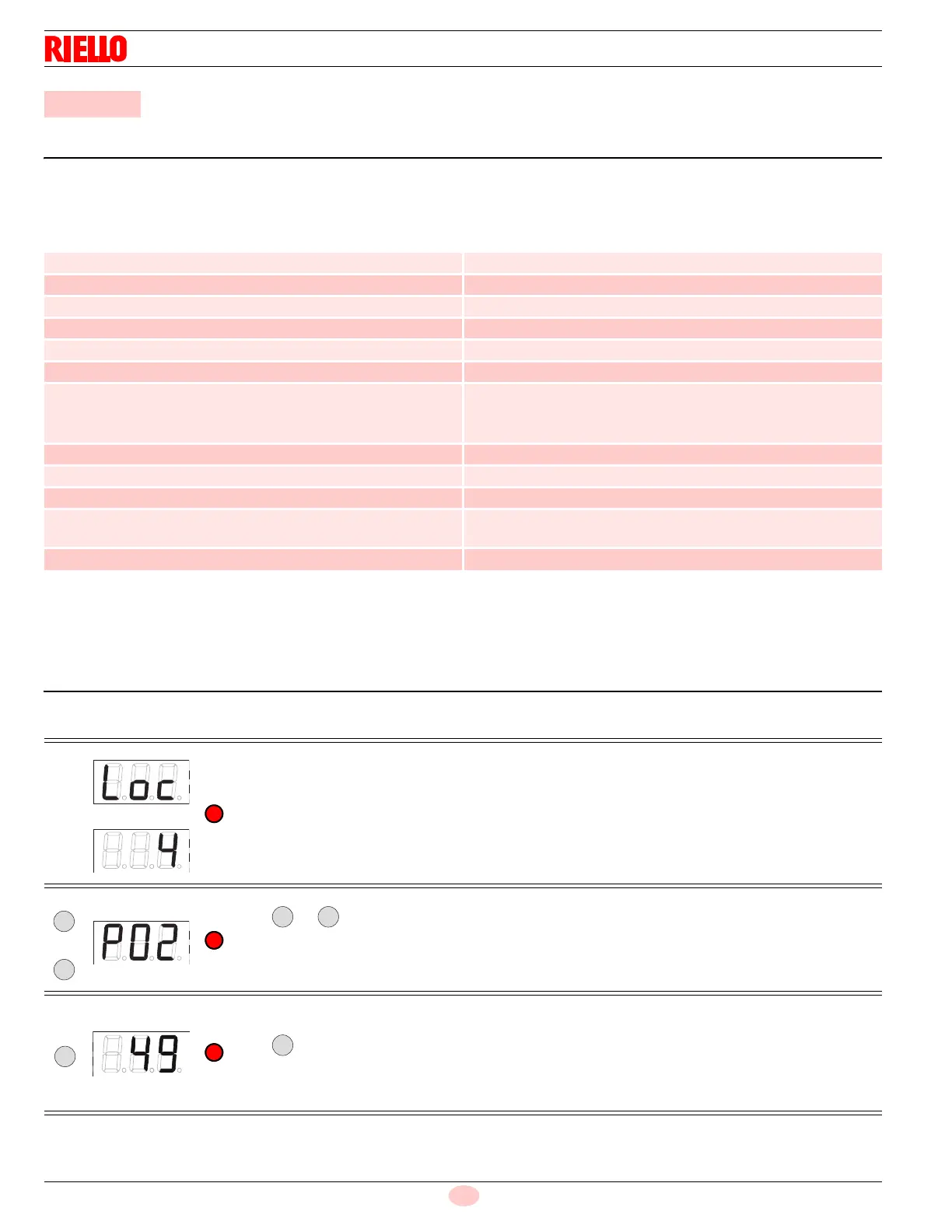
Only with modulation via analog signal
Press for display of the output position/actuator position where the error occurred.
Signal lamp lights up red.
Example: output position/actuator position 49.
 Loading...