Start-up, calibration and operation of the burner
31
20051011
5.8 Check of modulating operation
The burner leaves the factory set to 0-10 V signal for the modulat-
ing operation.
5.8.1 Display of preset output
Display is possible only when:
– in operating mode or standby,
– program sequence for modulating operation via analog preset
output.
Tab. P
5.8.2 Load controller inputs
Selection source preset output analog/3-position step input
(P654)
The following input signals can be selected and handled via param-
eter P654.
• 3-position step input (feedback potentiometer ASZxx.3x re-
quired/depending on the program sequence)
• 0...10 V
• 0...135
• 0...20 mA
• 4...20 mA with lockout at I <4 mA (AZL2...: Loc: 60)
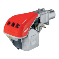
Press for display of the relative current position of the actuator.
Signal lamp blinks green.
Display shows .oP.
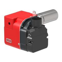
Press (1…3 seconds) for display of the relative current position.
Signal lamp blinks green.
The relative value .57 of the current position is displayed.
Example: value .57
PME7... with PWM fan:
Current speed 0 rpm = 0% display
Current speed corresponds to the rated load speed = 100% display
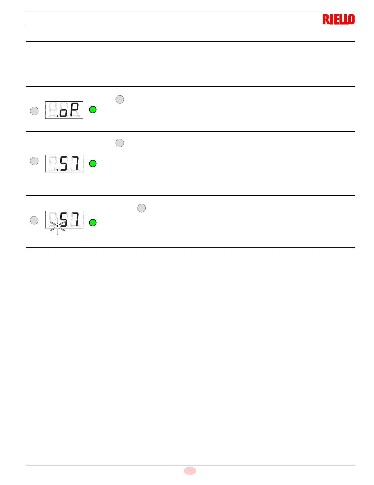
When pressing for >3 seconds, the point after the number begins to blink. When the button is released,
the value is displayed for 2 minutes.
Signal lamp blinks green.
Then, the normal display appears.
Display: value 57, point . blinks
A
A
 Loading...