Installation
21
20051011
4.8 Fuel supply
The burners are teamed with one-piece pneumatic proportioning
gas valves, via which the amount of gas delivered, and hence the
output produced, can be modulated.
A signal reporting pressure detected in the air circuit is carried to
the pneumatic gas valve, which delivers an amount of gas in pro-
portion to the airflow produced by the fan.
4.8.1 Air/gas mixer
Gas and combustive air are mixed inside the purging circuit (mix-
er), starting from the intake inlet.
Through the gas train, fuel is introduced into the intake air current
and optimal mixing commences with the aid of a mixer.
After having connected the compensation pipe (T) with the valve,
cover it again with the rubber protective device.
Explosion danger due to fuel leaks in the presence
of a flammable source.
Precautions: avoid knocking, attrition, sparks and
heat.
Make sure that the fuel interception tap is closed
before performing any operation on the burner.
The fuel supply line must be installed by qualified
personnel, in compliance with current standards
and laws.
Pipe (T) between valve-Venturi allows compensa-
tion to occur for accidental occlusion of the suction
line due to a reduction in gas delivered.
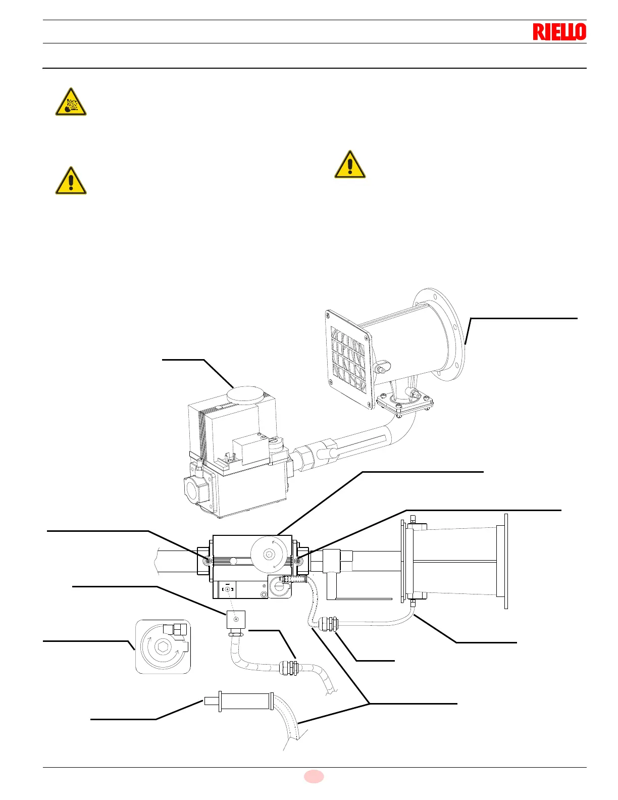
Fig. 15
20056648
Gas valve
Upstream gas pressure
test point (P1)
Minimum gas flow
adjustment on the
stabiliser (V2)
Compensation
Fair lead
Metallic protective
Compensation
Downstream pressure test point (P2)
Adjustment of maximum
Electrical valve
connection (XV1)
pipe (T)
Fair lead
device
pipe (T)
gas flow (V1)
Air/Gas mixer (Venturi)
in the suction line circuit
 Loading...