20051011
32
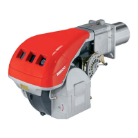
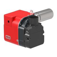
Start-up, calibration and operation of the burner
5.9 Factory wiring diagram
Control circuits
Burner operation may be controlled by either 120V or 24V control
systems.
The required controls must be connected to the burner as de-
scribed on the following.
120V control system
The burner provides it own power supply for the control circuits that
is switched internal from terminal 1(L) & 2 (N), do not apply power
on any other terminal or damaged to the control could occur.
The factory-installed jumper can be removed if a P.O.C device is
desired.
24V control system
If firing is to be controlled by a 24V operating system a 24V switch-
ing relay wired as shown in the diagram is required (not supplied –
sold separately).
The required 24V operating controls must be wired between the
thermostat terminals on the 24V-switching relay.
The factory-installed jumper can be removed if a P.O.C device is
desired.
If an external electrical source is utilized, the conversion burner,
when installed, must be electrically grounded with a solid green
wire to Earth Ground, in accordance with local codes or, in the ab-
sence of local codes, with the National Electrical Code ANSI/NFPA
70-1990 and the CSA Electrical Code.
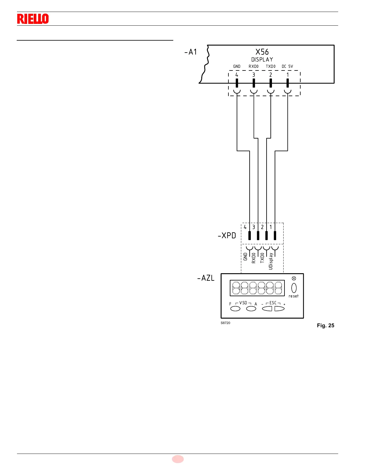
WIRING DIAGRAM OF KIT DISPLAY
Wiring key (Fig. 25)
A1 - Control box for the air/fuel ratio
AZL - Operator panel
XPD - Operator panel connector
!"#$
%
 Loading...