Start-up, calibration and operation of the burner
33
20051011
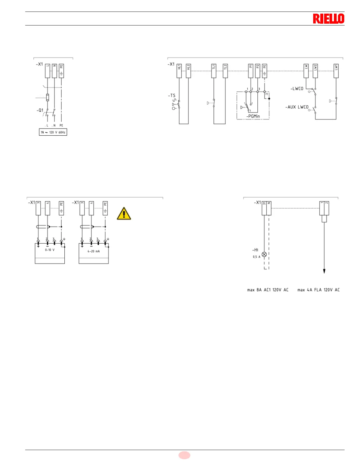
WIRING DIAGRAM
Wiring key (Fig. 26)
AUX LWCO Auxiliary low water control operation
H1 Remote lockout signal
LWCO Low water control operation
PGMin Minimum gas pressure switch
Q1 Single phase disconnecting switch
TS Safety thermostat
X1 Burner terminal strip
Fig. 26
S8724
ELECTRICAL POWER
TRIGGERING/SAFETY/DEVICES
POSSIBILITY OF EXTERNAL MODULATION INDICATORS
OPERATING
MANUAL
RESET HIGH
LIMIT CONTROL
GAS LOW PRESSURE
ATTENTION: USE ONLY COPPER CONDUCTORS
ATTENTION: CUSTOMER INSTALLATION
(NONTIME DELAY)
(TIME DELAY)
CONTROL
LOW WATER
CONTROL
AUXILIARY LOW
OPERATION
WATER CONTROL
SWITCH
BURNER LOCK OUT
LOAD CONTROLLER
LOAD CONTROLLER
OUTPUT
OUTPUT
BURNER LOCK OUT
OPERATION
VOLTAGE FREE
CONTACT OUTLET
ATTENTION:
for modulation 4-20 mA,
modify the internal parameters
AWG 12 min
30A
20A
 Loading...