20051011
16
Technical description of the burner
Key to Phases (Fig. 8, page 14):
Tab. J
3.8.1 Indication of diagnostics mode
Both lockout reset button and signal lamp are located in the control
panel.
There are 2 diagnostics choices:
1 Visual diagnostics: Indication of operating state or diagnostics
of cause of fault
2 Diagnostics: Via BCI to AZL2... display and operating unit
Visual diagnostics:
in normal operation, the different operating states are indicated in
the form of color codes according to the color code table given be-
low (Tab. K).
Indication of operating state
During startup, state indication takes place according to the Tab. K:
Tab. K
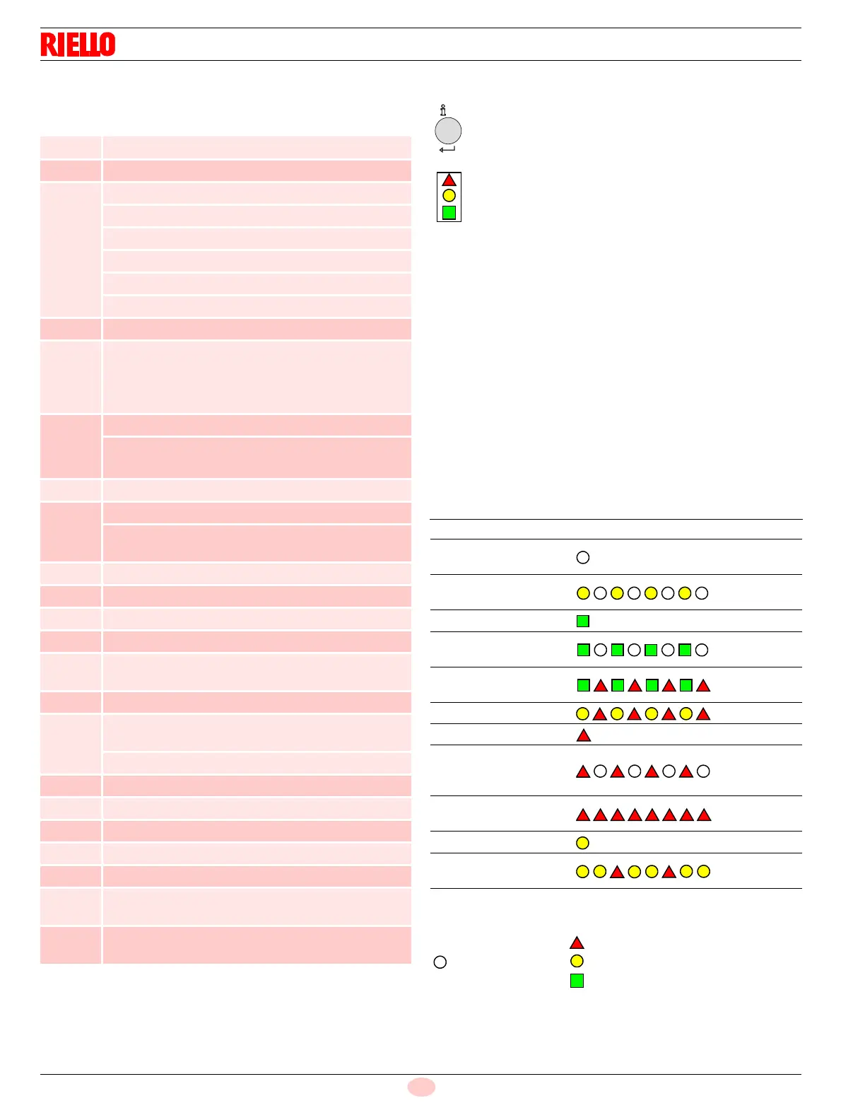
Key (Tab. K)
Phase
number
Function
LOC Lockout shutdown phase
OFF Standby, waiting for heat request
oP Part 1: request load controller OPEN
Part 2: modulation of fan motor speed toward high-fire
Part 3: high-fire reached
Part 4: request load controller CLOSED
Part 5: modulation of fan motor speed toward low-fire
Part 6: low-fired reached
10 Settling time, fan motor standby speed
21 Safety valve ON, air pressure switch in no-load posi-
tion
Check if POC is closed, fan motor speed is reduced to
0
22 Part 1: fan motor ON
Part 2: specified time air pressure switch
Message (timeout), stabilization of air pressure switch
24 Settling time, fan motor prepurge speed
30 Part 1: prepurge time without flame simulation test
Part 2: prepurge time with flame simulation test
(2.1 seconds)
36 Speed settling time, fan motor ignition load speed
38 Preignition time
40 Postignition time, parameter 257 + 0.3 seconds
42 Flame detection
44 Interval: end of ignition safety time and release of load
controller
72 Speed stabilization time, fan motor postpurge speed
74 Part 1: operation is ended, check if postpurging is pro-
grammed
Part 2: postpurge time
80 Test space is evacuated
81 Atmospheric pressure test
82 Test space is filled
83 Gas pressure test
90 Pressure switch-min open --> safety shutdown
*1 Valve proving, if P241 = 1 after main ON, lockout or
P234 (postpurge time) = 0 second
*2 Valve proving, if P241 = 1 and P234 (postpurge time)
>0 second
The lockout reset button (info button) is the key op-
erating element for resetting the burner control and
for activating/deactivating the diagnostics func-
tions.
The multicolor signal lamp is the key indicating el-
ement for visual diagnostics.
Color code table for multicolor signal lamp
State Color code Color
Waiting time,
other waiting states
OFF
Ignition phase,
ignition controlled
Blinking
yellow
Operation, flame o.k. Green
Operation,
flame not o.k.
Blinking
green
Extraneous light on
burner startup
Green - Red
Undervoltage Yellow - Red
Fault, alarm Red
Error code output (see
Error code Tab. Z,
page 42)
Blinking red
Interface diagnostics
Red flicker
light
Heating request Yellow
New program card
Yellow
Yellow - Red
nfo
...............................
...............................
...............................
...............................
Red
Yellow
Green
........
OFF
Steady on






 To Next Page