19
20135737
Installation
5.8 Positioning the probe - electrode
Make sure that the plate 3)(Fig. 14) is always inserted in the
flattening of the electrode 1).
Rest the probe insulator 4) against the air diffuser 2).
Tab. H
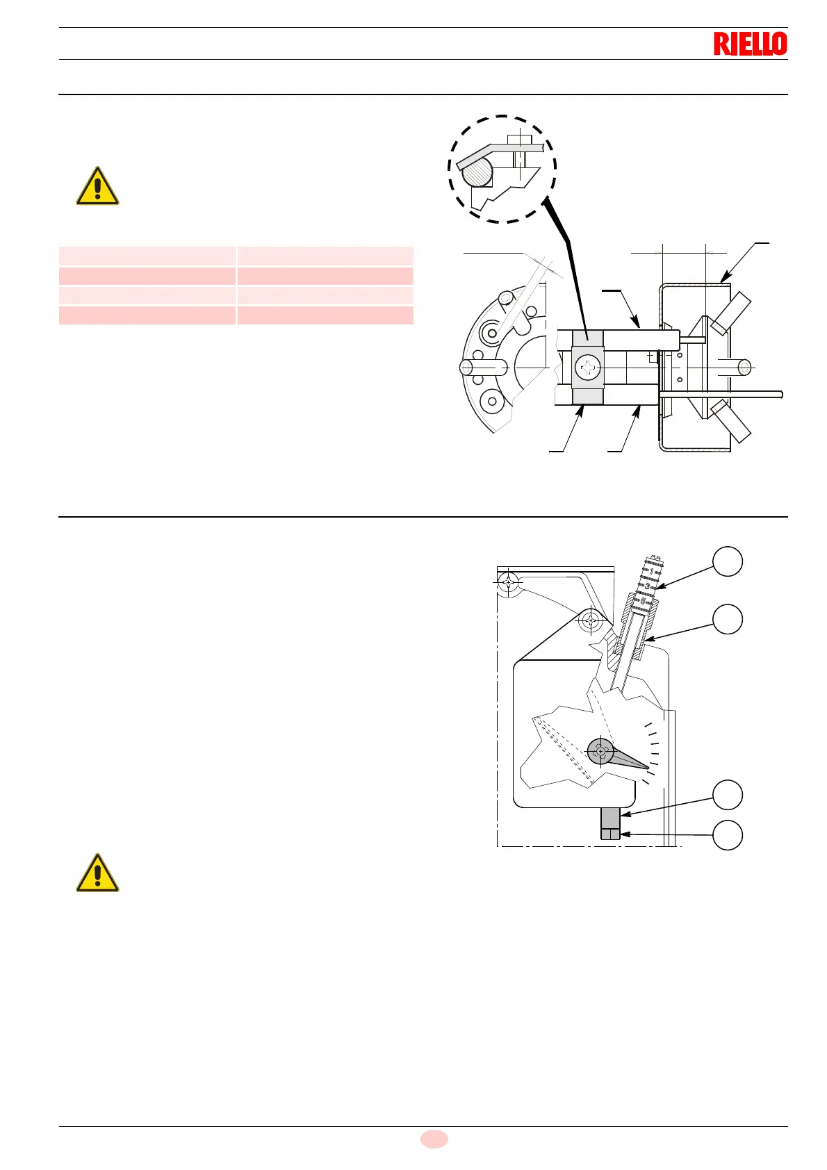
5.9 Air damper adjustment
The first start up should always be carried out using the screw
12)(Fig. 15), so that the 1st stage air damper position indicator is
greater than notch 1, (factory setting notch 1).
To vary the setting proceed as follows:
Bring the burner to the 2nd stage closing the connection T6-
T8 in the 4 pin plug (X4, electrical wiring of page 23).
The air damper, due to the thrust of the fan, is brought to the
2nd stage position relative to the factory calibration (screw 8
on notch 3).
Loosen the nut 9) and use the screw 8)(Fig. 15) to adjust
the 2nd stage air flow (see CO
2
values in the
Tab. T).
Bring the burner to the 1st stage opening the connection T6-
T8 in the 4 pin plug (X4, electrical wiring of page 23).
Adjust the 1st stage using the screw 12) after loosening
(clockwise) the nut 11)(Fig. 15) referring to the table below
for the CO
2
values.
Once the ideal setting has been reached, block ( anti-clock-
wise) the nut 11)(Fig. 15). When the burner stops, the air
damper, due to the pressure of its weight, automatically
closes, up to a max. flue depression of 0.5 mbar.
The burner output ratio between the 1st and 2nd stage
should be a maximum of 1: 2.
Example for BS3D: 2nd stage output required 140 kW;
Minimum 1st stage output not less than 70 kW.
In any event, the minimum burner output in the 1st stage
should not be less than the value indicated in the firing rate.
Example for BS3D: 2nd stage output required 110 kW;
Minimum 1st stage output not less than 65 kW (minimum of the
firing rate page 11).
Respect the positions shown in Tab. H.
Model A (mm) ± 0.3
BS1D 17
BS2D 30
BS3D 31
BS4D 31
Fig. 14
D6088
3.5 ± 0.3
A
1
2
3 4
To adjust the burner output of the 1st and 2nd
stage, follow the instructions below.
Fig. 15
8
9
12
11
0
6
1
2
3
4
5
D7181