23
20135737
Installation
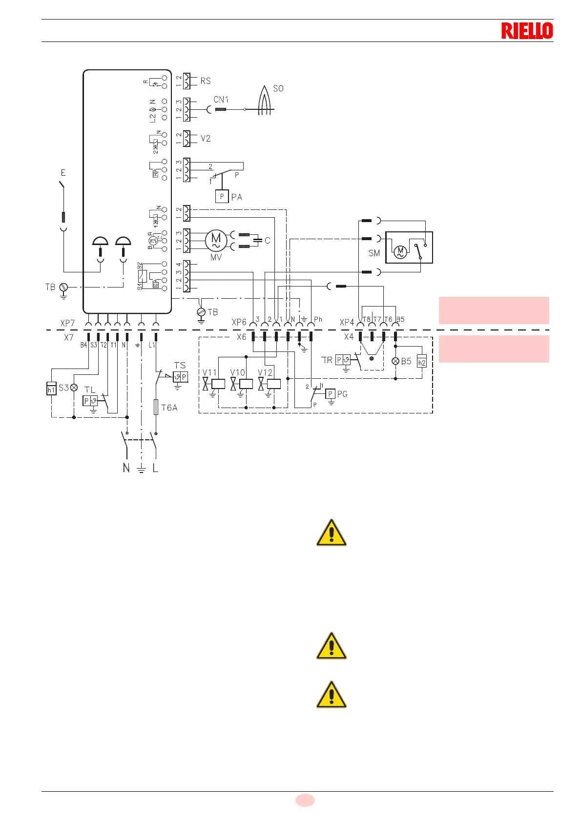
5.11.1 Electrical system carried out by the factory
Key to layout
B5 Signal 2nd stage operating
C Capacitor
CN1 Probe connector
EElectrode
h.. Hour counter
MV Motor
PA Minimum air pressure switch.
PG Minimum gas pressure switch
RS Remote reset
SM Air damper servomotor
SO Ionisation probe
S3 Lockout signal (230V - 0.5A max.)
T6A Fuse
TB Burner earth
TL Heat request thermostat
TR Adjustment thermostat 1st and 2nd stage
TS Safety thermostat
V10 Safety valve
V11 1st stage valve
V12 2nd stage valve
X.. Plug
XP.. Socket
CARRIED OUT
IN THE FACTORY
Fig. 18
230V ~ 50Hz
CONTROL BOX
D4627
Master
switch
Brown
Blue
Black
TO BE DONE BY
BY THE INSTALLER
Do not invert the neutral with the phase in the
electrical supply line.
Check that the electrical supply of the burner
corresponds to that shown on the identifica-
tion label and in this manual.
The section of the conductors must be at
least 1mm
2
. (Unless requested otherwise by
local standards and legislation).
Connect the 2nd stage thermostat (TR) to the
terminals T6 - T8 removing the jumper.
Check the burner stops by opening the thermo-
stats and check it locks out by opening the con-
nector (CN1) (Fig. 18) inserted in the probe's red
wire, located on the outside of the control box.
If the cover is still on, remove it and proceed with
the electric wiring following the wiring diagrams.
Use flexible cables in compliance with EN 60 335-
1 standards.