1892
1
GB
INDEX
1. BURNER DESCRIPTION
One stage gas oil burner.
1.1 BURNER EQUIPMENT
Flange with insulating gasket . . . No. 1 Screw and nuts for flange to be fixed to boiler . . No. 4
Screw and nuts for flange . . . . . . No. 1 Flexible oil pipes with nipples . . . . . . . . . . . . . . No. 2
7 pin plug . . . . . . . . . . . . . . . . . . No. 1
1. BURNER DESCRIPTION. . . . . . . . . . . . 1
1.1 Burner equipment . . . . . . . . . . . . . . . . . 1
2. TECHNICAL DATA . . . . . . . . . . . . . . . . 2
2.1 Technical data . . . . . . . . . . . . . . . . . . . . 2
2.2 Overall dimensions. . . . . . . . . . . . . . . . . 2
2.3 Working field . . . . . . . . . . . . . . . . . . . . . 2
3. INSTALLATION . . . . . . . . . . . . . . . . . . . 3
3.1 Boiler fixing . . . . . . . . . . . . . . . . . . . . . . 3
3.2 Fuel supply . . . . . . . . . . . . . . . . . . . . . . 3
3.3 Hydraulic systems . . . . . . . . . . . . . . . . . 4
3.4 Electrical wiring . . . . . . . . . . . . . . . . . . . 5
4. WORKING . . . . . . . . . . . . . . . . . . . . . . . 6
4.1 Combustion adjustment. . . . . . . . . . . . . . 6
4.2 Recommended nozzles. . . . . . . . . . . . . . 6
4.3 Combustion head setting. . . . . . . . . . . . . 7
4.4 Electrodes adjustment. . . . . . . . . . . . . . . 7
4.5 Pump pressure and air output . . . . . . . . . 7
4.6 Burner start-up cycle. . . . . . . . . . . . . . . . 8
5. MAINTENANCE . . . . . . . . . . . . . . . . . . . 8
6. FAULTS / SOLUTIONS . . . . . . . . . . . . . . 9
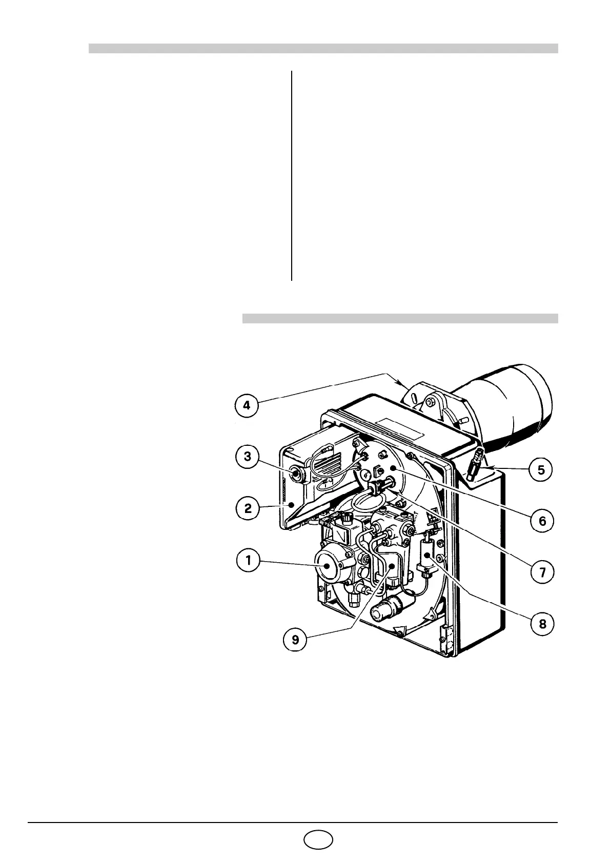
1 – Oil pump
2 – Control-box
3 – Reset button with lock-out
lamp
4 – Flange with insulating
gasket
5 – Air damper adjustment assembly
6 – Nozzle holder assembly
7 – Photoresistance
8 – Hydraulic jack
9 – Start delaying device
■
DIN Certification No. : 5G265/98
as EN 267.
■
The burner meets protection level of IP 40, EN 60529.
■
Burner with CE marking in conformity with EEC directives: EMC 89/336/EEC, Low Voltage 73/23/EEC,
Machines 98/37/EEC and Efficiency 92/42/EEC.
Fig. 1
S7218