J
Jeffrey GibsonAug 27, 2025
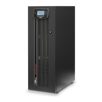
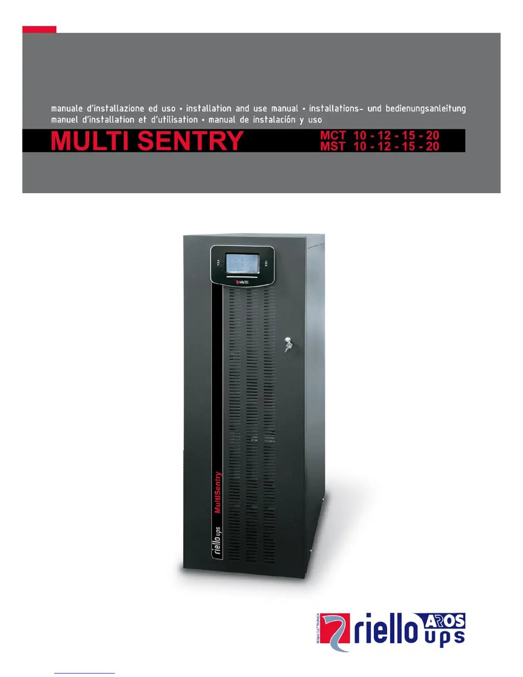
What does the S06 code on my Riello MCT 20 display mean?
- TTeresa AndersonAug 27, 2025
This issue occurs because of discharged batteries. You should wait for the batteries to recharge, or you can force power on from the System On menu.