Technical description of the burner
4.6 Test boiler
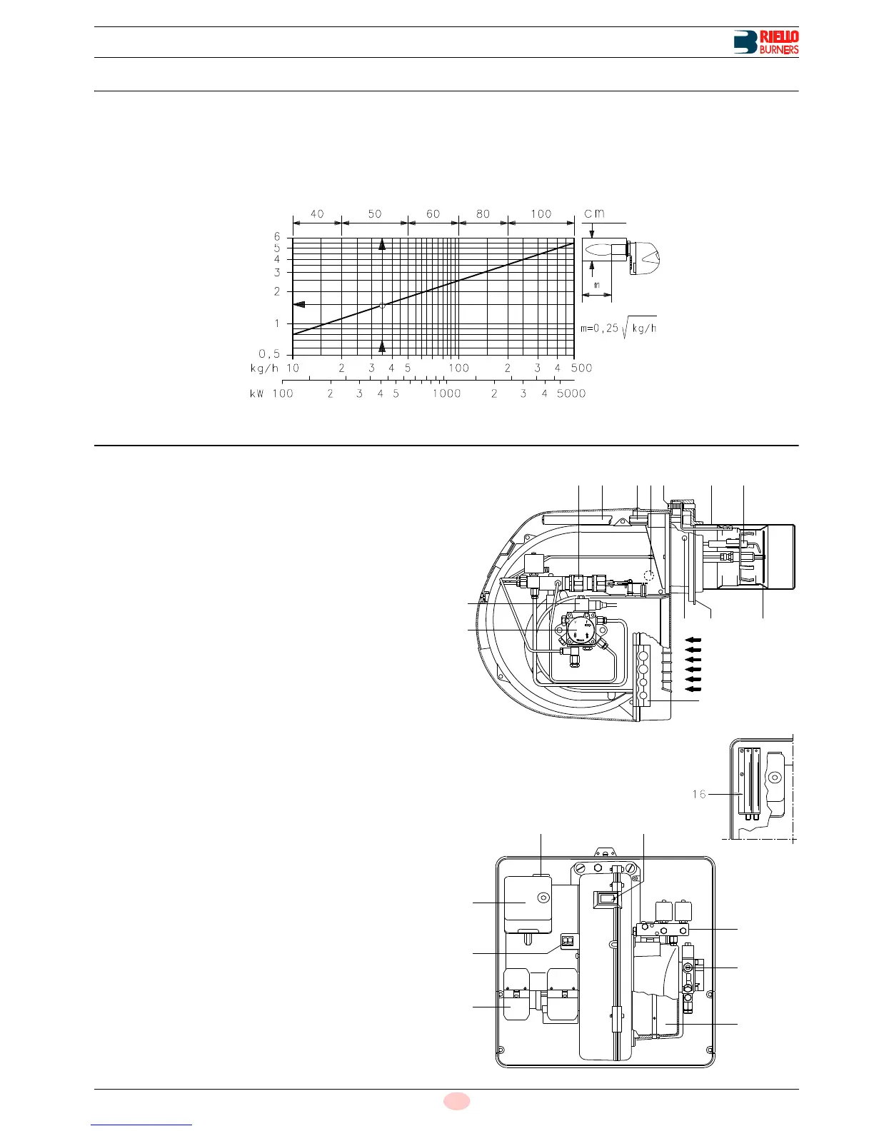
The firing rate was set in relation to special test boilers in accord-
ance with the methods defined in EN 267 standards.
Fig. 3 indicates the diameter and length of the test combustion
chamber.
Example
delivery 35 kg/hour: diameter = 50 cm; length = 1.5 m.
Whenever the burner is operated in a much smaller commercial-
ly-available combustion chamber, a preliminary test should be
performed.
4.7 Burner description
1 Ignition electrodes
2 Combustion head
3 Screw for combustion head adjustment
4 Photocell for flame presence control
5 Screw for fixing fan to flange
6 Slide bars for opening the burner and inspecting the com-
bustion head
7 Hydraulic cylinder for regulation of the air gate valve in 1st
and 2nd stage positions. When the burner is not operating
the air gate valve is fully closed in order to reduce heat dis-
persion from the boiler due to the flue draught which draws
air from the fan suction inlet.
8 Safety solenoid valve
9Pump
10 Plate prearranged to drill 4 holes for the passage of hoses
and electrical cables.
11 Air inlet to fan
12 Fan pressure test point
13 Boiler mounting flange
14 Flame stability disk
15 Flame inspection window
16 Extensions for slide bars 6)
17 Motor contactor and thermal cut-out reset button
18 Control box with lock-out pilot light and lock-out reset button
19 Two switches:
- one “burner off - on”
- one for “1st - 2nd stage operation”
20 Plugs for electrical connections
21 Air gate valve
22 Pump pressure adjustment
23 1st and 2nd stage valve assembly
Two types of burner failure may occur:
Control box lock-out
if the control box 18)(Fig. 4) pushbutton (red led) lights up, it
indicates that the burner is in lock-out. To reset, hold the
pushbutton down for between 1 and 3 seconds.
Motor trip
pressing the pushbutton on thermal cutout 17)(Fig. 4).