Installation
5.9 Nozzle installation
5.9.1 Choice of nozzles for 1st and 2nd stage
The burner complies with the emission requirements of the
EN 267 standard.
In order to guarantee that emissions do not vary, recommended
and/or alternative nozzles specified by Riello in the Instruction
and warning booklet should be used.
Both nozzles must be chosen from among those listed in Tab. E
and Tab. F.
The first nozzle determines the delivery of the burner in the 1st
stage.
The second nozzle works together with the 1st nozzle to deter-
mine the delivery of the burner in the 2nd stage.
The deliveries of the 1st and 2nd stages must be contained within
the value range indicated on page 2. Use nozzles with a 60°
spray angle at the recommended pressure.
The two nozzles usually have equal deliveries, but the 1st stage
nozzle may have the following specifications if required:
a delivery less than 50% of the total delivery whenever the
back-pressure peak must be reduced at the moment of fir-
ing;
a delivery higher than 50% of the total delivery whenever the
combustion during the 1st stage must be improved.
Example
(gas oil):
Boiler output = 270 kW - efficiency 90%
Output required by the burner =
270 : 0.9 = 300 kW
300 : 2 = 150 kW per nozzle
therefore, two equal, 60°, 12 bar nozzles are required:
1° = 3.00 GPH - 2° = 3.00 GPH,
or the following two different nozzles:
1° = 2.50 GPH - 2° = 3.50 GPH,
or:
1° = 3.50 GPH - 2° = 2.50 GPH.
5.9.2 Tables nozzles
(Gas oil 100%)
Tab. E
(1)
We get the indicated delivery when both nozzles are working
and gas oil has the following characteristics: density 0.84 kg/
dm
3
- viscosity 4.2 cSt/20 °C - temperature 10 °C.
(Kerosene 100%)
Tab. F
(1)
We get the indicated delivery when both nozzles are working
and kerosene has the following characteristics: density 0.81
kg/dm
3
- viscosity 1.6 cSt/20 °C - temperature 25 °C.
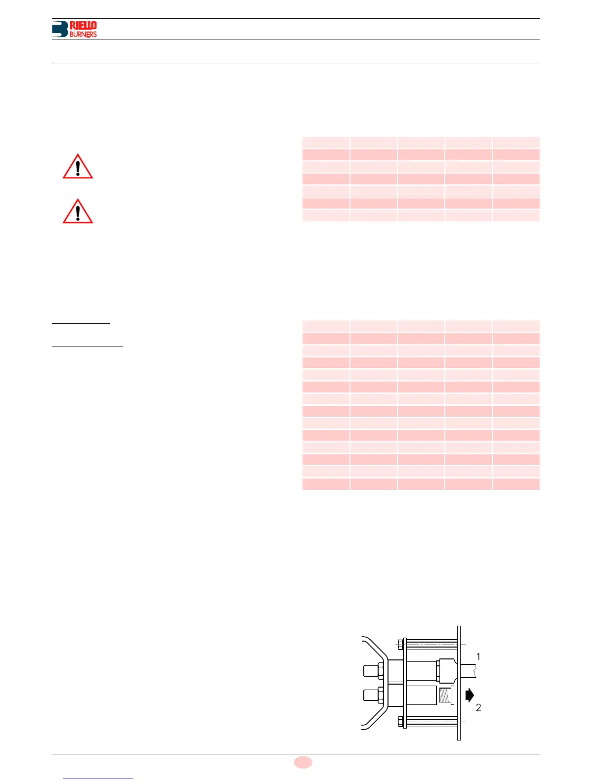
5.9.3 Nozzle assembly
At this stage of installation the burner is still disassembled from
the blast tube; it is therefore possible to fit two nozzles with the
box spanner 1)(Fig. 11) (16 mm), after having removed the plas-
tic plugs 2), fitting the spanner through the central hole in the
flame stability disk.
The use of nozzles other than those specified by
Riello S.p.A. and inadequate regular maintenance
may result into emission limits non-conforming to
the values set forth by the regulations in force, and
in extremely serious cases, into potential hazards
to people and objects.
The manufacturing company shall not be liable for
any such damage arising from nonobservance of
the requirements contained in this manual.
GPH
kg/h
(1)
kW
12 bar
10 bar 12 bar 14 bar
3.00 11.5 12.7 13.8 150.6
3.50 13.5 14.8 16.1 175.5
4.00 15.4 17.0 18.4 201.6
4.50 17.3 19.1 20.7 226.5
5.00 19.2 21.2 23.0 251.4
5.50 21.1 23.3 25.3 276.3
6.00 23.1 25.5 27.7 302.4
GPH
kg/h
(1)
kW
10 bar
8 bar 9 bar 10 bar
2.50 7.31 7.79 8.25 99.0
2.75 8.04 8.57 9.07 108.6
3.00 8.77 9.35 9.90 118.6
3.25 9.51 10.13 10.72 128.4
3.50 10.24 10.91 11.55 138.3
4.00 11.70 12.47 13.20 158.0
4.50 13.16 14.03 14.85 177.8
5.00 14.62 15.58 16.50 197.8
5.50 16.09 17.14 18.15 217.4
6.00 17.55 18.70 19.80 237.1
6.50 19.01 20.26 21.44 256.8
7.00 20.47 21.82 23.09 276.5
7.50 21.94 23.38 24.74 296.3
8.00 23.40 24.93 26.39 316