Start-up, calibration and operation of the burner
8.1 Notes on safety for the first start-up
8.2 Burner calibration
8.2.1 Firing
Set switch 1)(Fig. 24) to "ON".
During the first firing, during the passage from the 1st to the 2nd
stage, there is a momentary lowering of the fuel pressure caused
by the filling of the 2nd stage nozzle tubing.
This lowering of the fuel pressure can cause the burner to lockout
and can sometimes give rise to pulsations.
Once the following adjustments have been made, the firing of the
burner must generate a noise similar to the noise generated dur-
ing operation.
If one or more pulsations or a delay in firing in respect to the
opening of the fuel solenoid valve occur, see the suggestions pro-
vided on page 30: causes 31 to 41.
8.2.2 Operation
The optimum calibration of the burner requires an analysis
of the flue gases at the boiler outlet and interventions on the
following points:
• 1st and 2nd nozzles
See the information listed on page 16.
• Combustion head
The adjustment of the combustion head already carried out need
not be altered unless the 2nd stage delivery of the burner is
changed.
• Pump pressure (gas oil)
12 bar: This is the pressure calibrated in the factory which is
usually sufficient for most purposes. Sometimes, this
pressure must be adjusted to:
10 bar: in order to reduce fuel delivery. This adjustment is pos-
sible only if the surrounding temperature remains above
0°C. Never calibrate to pressures below 10 bar, at which
pressures the cylinders may have difficulty in opening;
14 bar: in order to increase fuel delivery or to ensure firings even
at temperatures of less than 0°C. In order to adjust pump
pressure, use the screw 5)(Fig. 20).
• Pump pressure (kerosene)
10 bar: maximun pressure for kerosene.
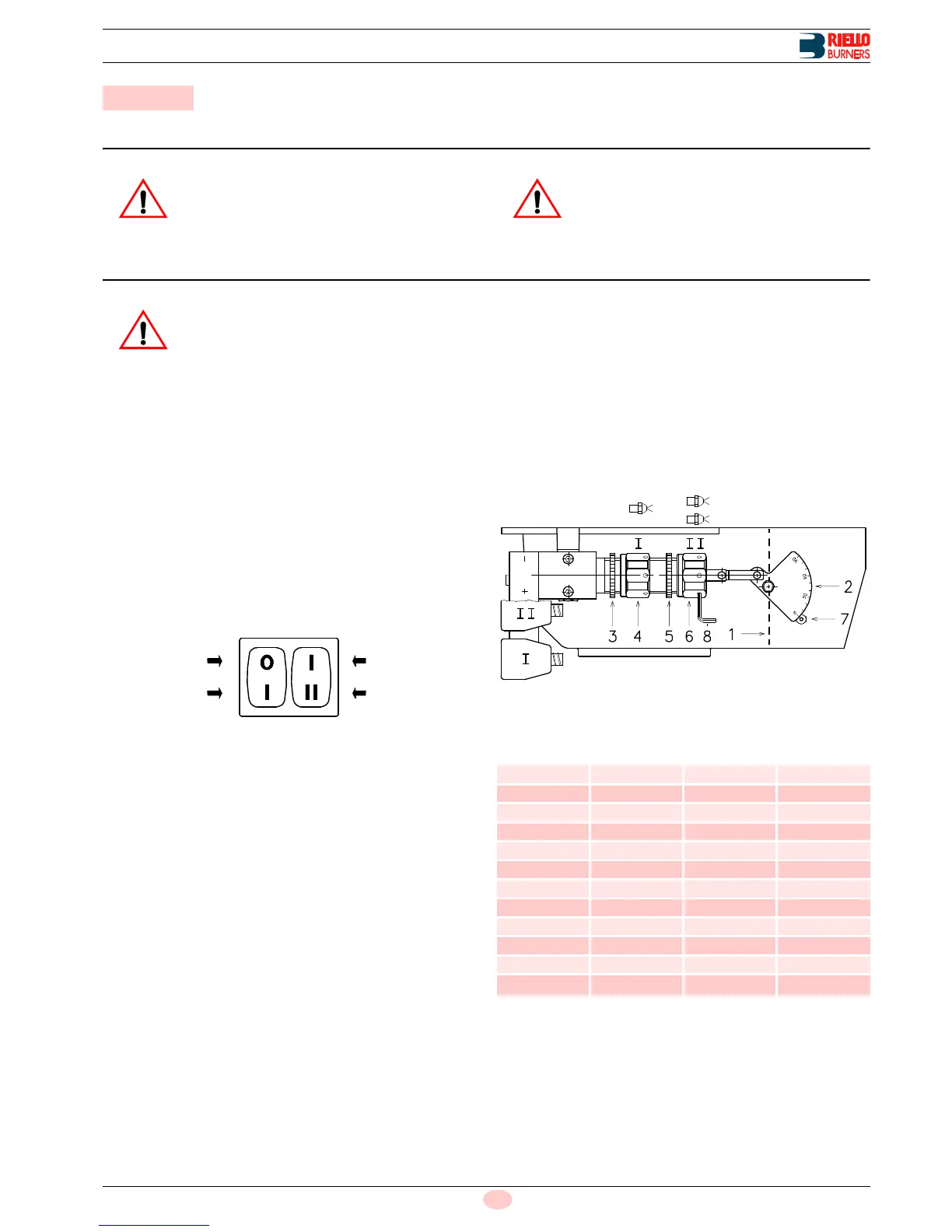
• 1st stage fan air gate valve
Keep the burner operating at 1st stage by setting the switch 2)
(Fig. 24) to the 1st stage position. Opening of the air gate valve
1)(Fig. 25) must be adjusted in proportion to the selected nozzle:
the index 7)(Fig. 25) must be aligned with the specified in
(Tab. J). This adjustment is achieved by turning the hex element
4):
– in rh direction (- sign) the opening is reduced;
– in lh direction (+ sign) the opening increases.
1st STAGE
Tab. J
= Notch Nr.
(1)
With shutter 4)(Fig. 10 on page 15) retracted.
Example:
1st stage nozzle 5.00 GPH:
notch 23° aligned with index 7 (Fig. 25).
When the adjustment is terminated lock the hex element 4) with
the ring nut 3).
8 Start-up, calibration and operation of the burner