Start-up, calibration and operation of the burner
8.3 Burner operation
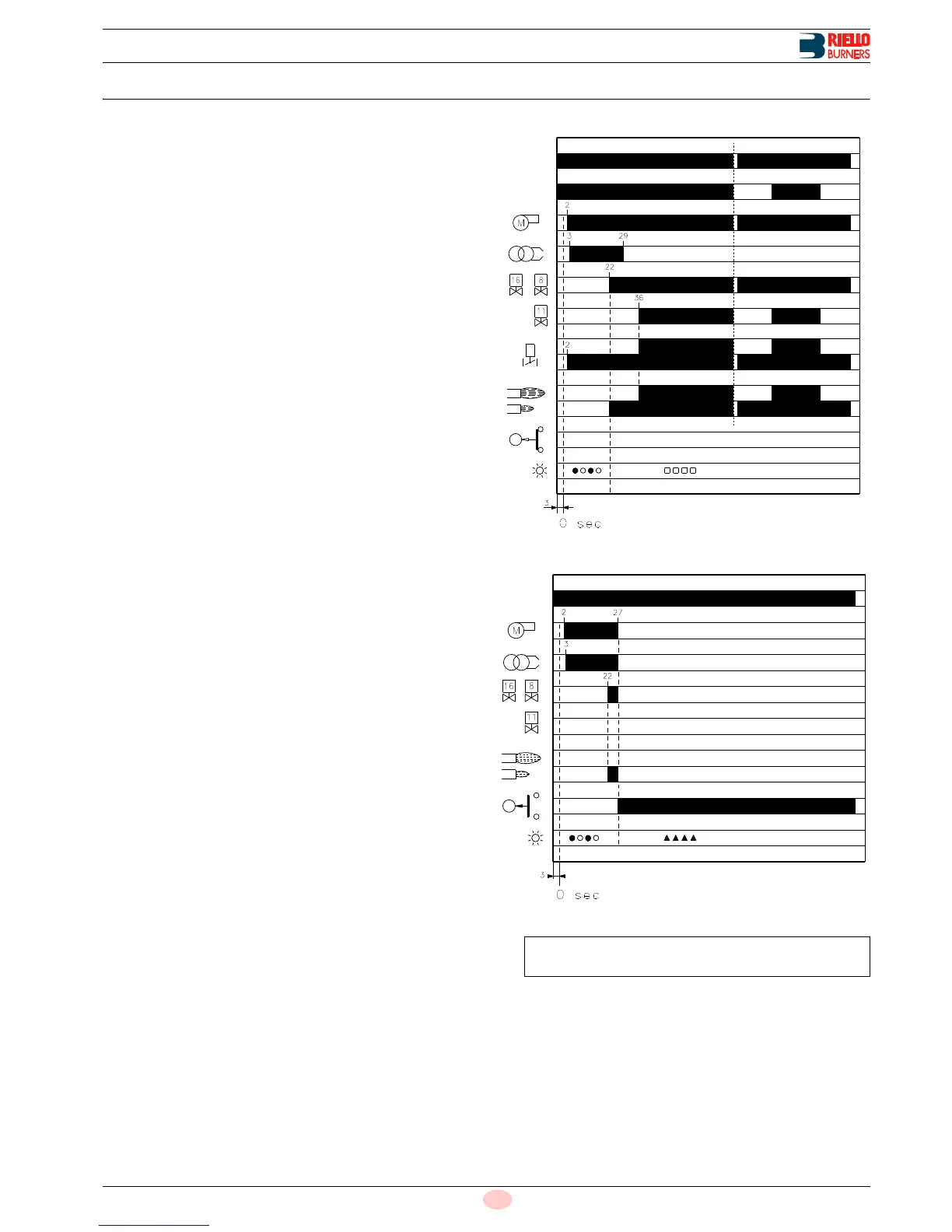
8.3.1 Burner starting
Starting phases with progressive time intervals shown in sec-
onds:
• Control device TL closes.
• After about 3s:
• 0 s : The control box starting cycle begins.
• 2 s : The fan motor starts.
• 3 s : The ignition transformer is connected.
The pump 3) sucks the fuel from the tank through the piping
1) and the filter 2) and pumps it under pressure to delivery.
The piston 4) rises and the fuel returns to the tank through the
piping 5) - 7). The screw 6) closes the by-pass heading to-
wards suction and the solenoid valves 8) - 11) - 16), de-ener-
gized, close the passage to the nozzles.
The hydraulic cylinder 15), piston A, opens the air gate valve:
pre-purging begins with the 1st stage air delivery.
• 22 s : The solenoid valves open 8) - 16); and the fuel passes
through the piping 9) and filter 10) and is then sprayed out
through the nozzle, igniting when it comes into contact with
the spark. This is the 1st stage flame.
• 29 s : The ignition transformer switches off.
• 36 s : If the control device TR is closed or has been replaced
by a jumper wire, the 2nd stage solenoid valve 11) is opened
and the fuel enters the valve 12) and raises the piston which
opens two passages: one to piping 13), filter 14), and the 2nd
stage nozzle, and the other to the cylinder 15), piston B, that
opens the fan air gate valve in the 2nd stage.
The starting cycle comes to an end.
8.3.2 Firing failure
If the burner does not fire, it goes into lockout within 5s of the
opening of the 1st nozzle valve and 30 s after the closing of con-
trol device TL.
The control box red pilot light will light up.
8.3.3 Undesired shutdown during operation
If the flame goes out during operation, the burner shuts down au-
tomatically within 1 second and automatically attempts to start
again by repeating the starting cycle.
*
Off Yellow Green Red
For further details see page 29.