Appendix - Accessories (optional)
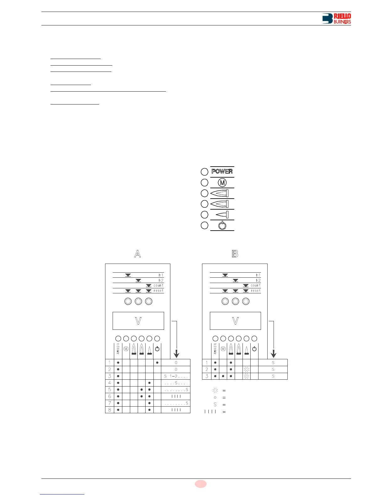
The STATUS unit has three functions:
1 BURNER OPERATING HOURS AND THE NUMBER OF
FIRINGS ARE SHOWN ON DISPLAY V
– Total operating hours: press button "h1".
– 2nd stage operating hours
: press button "h2".
– 1st stage operating hours: total hours - 2nd stage operating
hours
– Number of firings
: press button "count".
– Resetting operating hours and number of firings: press the
three “reset” buttons simultaneously.
– Non-volatile memory
: the operating hours and the number of
firings will remain in the memory even in the case of electrical
power failures.
2 INDICATES THE TIMES RELATIVE TO THE FIRING
STAGE
The leds illuminate in the following sequence, see Fig. 2:
WITH CONTROL DEVICE TR CLOSED:
1 Burner off, TL open
2 Control device TL closed
3 Motor start: seconds count starts on read-out V
4 1st stage valve energized
5 2nd stage valve energized: seconds count stops on read-
out V
6 10 seconds after stage 5 the code I I I I will appear on the
read-out: this indicates that the starting phase is terminated.
WITH CONTROL DEVICE TR OPEN:
1 Burner off, TL open
2 Control device TL closed
3 Motor start: seconds count starts on read-out V
4 1st stage valve energized
7 30 seconds after stage 4: seconds count stops on read-
out V
8 -10 seconds after stage 7 the code I I I I will appear on the
read-out: this indicates that the starting phase is termi-
nated.
The times, in seconds, shown on read-out V, indicate the succes-
sion of the various starting stages described on page 13.
3 IN THE CASE OF BURNER MALFUNCTIONS, THE STA-
TUS PANEL INDICATES THE EXACT TIME AT WHICH
THE FAULT OCCURRED
There are 3 possible combinations of illuminated leds.
For the causes of the malfunction refer to the numbers shown be-
tween brackets; see the legend for interpretation of the numbers.
1 . . . . . . . . . . .(8 ÷ 9)
2 . . . . . . . . . . .(10 ÷ 28)
3 . . . . . . . . . . .(31)
Key to symbols: