4
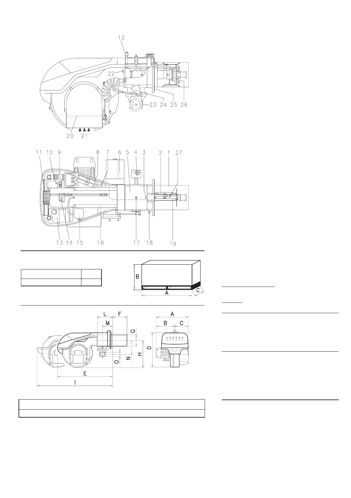
BURNER DESCRIPTION (A)
1 Combustion head
2 Ignition electrode
3 Screw for combustion head adjustment
4 High gas pressure switch
5 Sleeve
6 Servomotor controlling the gas butterfly valve and of
air damper (by means of a variable profile cam mech-
anism).
When the burner is not operating the air damper is
fully closed in order to reduce heat dispersion from
the boiler due to the flue draught which draws air
from the fan suction inlet.
7 Plug-socket on ionisation proble (flame rod) cable
8 Extensions for slide bars 16) (with kit)
9 Motor contactor and thermal overload with reset but-
ton
10 Power switch for different operations:
automatic - manual - off
Switch for:
Power increase - power reduction
11 Terminal strip
12 Pilot burner attachment
13 Flame safeguard (flame relay) with lock-out pilot light
and lock-out reset button
14 Flame inspection window
15 Low air pressure switch
(differential operating type)
16 Slide bars for opening the burner and inspecting the
combustion head
17 Gas pressure test point and head fixing screw
18 Air pressure test point
19 Flame sensor probe (flame rod)
20 Air damper
21 Air inlet to fan
22 Screws securing fan to sleeve
23 Gas input pipework
24 Gas butterfly valve
25 Boiler mounting flange
26 Flame stability disk
27 Ignition pilot
Two types of burner failure may occur:
Flame saf
eguard lock-out: if the flame relay 13)(A) push-
button lights up, it indicates that the burner is in lock-out.
To reset, press the pushbutton.
Motor tr
ip: release by pressing the pushbutton on ther-
mal relay 9)(A).
PACKAGING - WEIGHT (B)
- Approximate measure-
ments
• The burner is shipped skid mounted Outer dimen-
sions of packaging are indicated in (B).
• The weight of the burner complete with packaging is
indicated in Table (B).
MAX. DIMENSIONS (C)
-
Approximate measurements
The maximum dimensions of the burners are given in
(C).
Bear in mind that inspection of the combustion head
requires the burner to be opened and the rear part with-
drawn on the slide bars.
The maximum dimension of the burner, without casing,
when open is give by measurement I.
STANDARD EQUIPMENT
1 - Gas train flange
1 - Flange gasket
4 - Flange fixing screws
1 - Burner head gasket
4 - Screws to secure the burner flange to the boiler:
1/
2
W x
1
3
/
8
”
1 - Cap for combustion head
1 - Disc for combustion head
1 - Instruction booklet
1 - Spare parts list
(A)
ABClbs
49
31
/
32
“28
1
/
2
“30
29
/
32
“
181
D36
(B)
ABCDEFGHILMNO
26
13
/
16
“14
13
/
32
“12
13
/
32
“21
27
/
32
“33
11
/
16
“14
21
/
32
“8
3
/
4
“16
15
/
16
“51
21
/
32
“9
1
/
16
“5
29
/
32
”7
5
/
16
”
2”
(C)
D2430
D731




 To Next Page