20144599
16
Installation
5.4 Operating position
5.5 Preparing the boiler
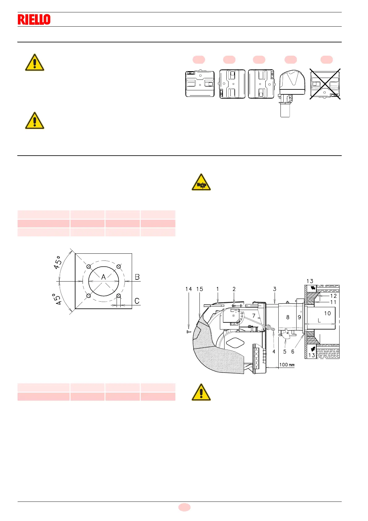
5.5.1 Boring the boiler plate
Pierce the closing plate of the combustion chamber, as in Fig. 9.
The position of the threaded holes can be marked using the
thermal insulation screen supplied with the burner.
Tab. D
5.5.2 Blast tube length
The length of the blast tube must be selected according to the
indications provided by the manufacturer of the boiler, and in any
case it must be greater than the thickness of the boiler door
complete with its fettling. The range of lengths available, L (mm),
is as follows:
Tab. E
For boilers with front flue passes 15) or flame inversion chamber,
a protection in refractory material 13) must be inserted between
the boiler fettling 14) and the blast tube 12).
This protective fettling must not compromise the extraction of the
blast tube.
For boilers with a water-cooled front piece, a refractory lining 13)-
14)(Fig. 10) is not necessary, unless expressly requested by the
boiler manufacturer.
5.5.3 Securing the burner to the boiler
Separate the combustion head from the rest of the burner
(Fig. 10):
Remove screw 14) and extract cover 15).
Disengage the articulated coupling 4) from the graduated
sector 5)
Remove the screws 2) from the two slide bars 3).
Remove the screw 1) and draw the burner back on the slide
bars 3) by about 100mm.
Disconnect the probe and electrode cables and then slide
the burner completely out of the slide bars, after removing
the split pin from the slide bar 3).
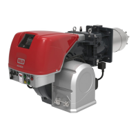
The burner is set up to operate only in
positions 1, 2, 3 and 4 (Fig. 8).
Installation 1 is preferable, as it is the only
one that allows the maintenance operations
as described in this manual.
Installations 2, 3 and 4 permit operation but
make maintenance and inspection of the
combustion head more difficult.
Any other position could compromise the
correct operation of the appliance.
Installation 5 are forbidden for safety
reasons.
mm A B C
RS 28 160 224 M 8
RS 38 160 224 M 8
RS 50 160 224 M 8
mm RS 28 RS 38 RS 50
Standard 216 216 216
Elongated 351 351 351
Provide an adequate lifting system.
The seal between burner and boiler must be
airtight.
 Loading...