20144599
22
Installation
5.10 Electrical connections
Notes on safety for the electrical wiring
Before carrying out any maintenance, cleaning or checking
operations:
Use flexible cables according to EN 60 335-1 Regulations:
•if in PVC sheath, use at least H05 VV-F
•if in rubber sheath, use at least H05 RR-F.
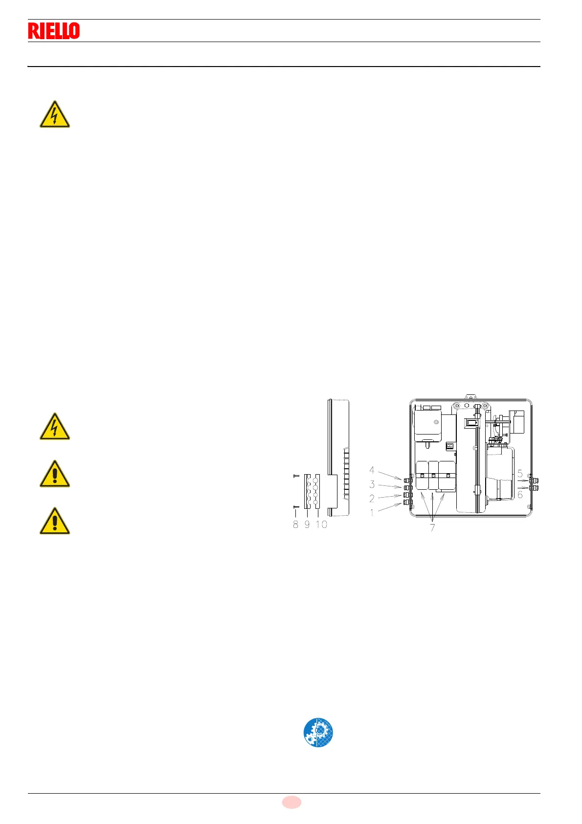
All the cables to be connected to the plugs 7)(Fig. 21) of the
burner are passed through cable grommets supplied with the unit
to be inserted in the holes of the plate, left or right, after having
unscrewed the screws 8), opened the plate at parts 9 and 10 and
removed the thin diaphragm that closes the holes.
The use of the cable grommets and the pre-blanked holes can be
done in different manners; for example:
RS 28 and RS 38 single-phase
1 Pg 11 Single-phase power supply
2Pg 11 Gas valves
3 Pg 9 TL remote control
4 Pg 9 TR remote control
5 Pg 11 Gas pressure switch or valve leak detection
control device
RS 38 three-phase and RS 50
1 Pg 11 Three-phase power supply
2 Pg 11 Single-phase power supply
3 Pg 9 TL remote control
4 Pg 9 TR remote control
5Pg 11 Gas valves
6 Pg 11 Gas pressure switch or valve leak detection
control device
The electrical wiring must be carried out with the electrical supply disconnected.
Electrical wiring must be made in accordance with the regulations currently in force in the country of destination
and by qualified personnel. Refer to the wiring diagrams.
The manufacturer declines all responsibility for modifications or connections different from those shown in the
wiring diagrams.
Check that the electrical supply of the burner corresponds to that shown on the identification label and in this
manual.
The burner has been type-approved for intermittent use.
This means they should compulsorily be stopped at least once every 24 hours to enable the control box to
perform checks of its own start-up efficiency. Normally, burner stopping is guaranteed by the boiler's thermostat/
pressure switch.
If this is not the case, a time switch should be fitted in series to TL to stop the burner at least once every 24 hours.
Refer to the wiring diagrams.
The electrical safety of the device is obtained only when it is correctly connected to an efficient earthing system,
made according to current standards. It is necessary to check this fundamental safety requirement. In the event of
doubt, have the electrical system checked by qualified personnel. Do not use the gas tubes as an earthing system
for electrical devices.
The electrical system must be suitable for the maximum power absorption of the device, as indicated on the label
and in the manual, checking in particular that the section of the cables is suitable for that level of power
absorption.
For the main power supply of the device from the electricity mains:
- do not use adapters, multiple sockets or extensions;
- use a multiple pole switch with at least a 3 mm gap between the contacts (overvoltage category III), as
envisaged by the present safety standards.
Do not touch the device with wet or damp body parts and/or in bare feet.
Do not pull the electric cables.
Disconnect the electrical supply from the burner
by means of the main system switch.
Close the fuel shut-off valve.
Avoid condensate, ice and water leaks from
forming.
After carrying out maintenance, cleaning or
checking operations, reassemble the cover and
all the safety and protection devices of the burner.
 Loading...