17
20144599
Installation
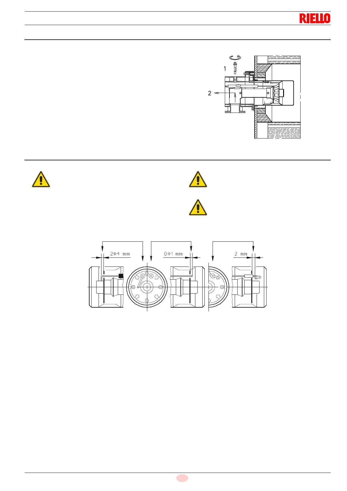
5.6 Access to head internal part
In order to reach inside the combustion head (Fig. 11) proceed as
follows:
remove the screw 1) and the internal part 2).
Fix the flange 9)(Fig. 10) to the plate of the boiler interposing the
insulating flange gasket 6)(Fig. 10) supplied with the unit. Use the
4 screws, also supplied with the unit, after first protecting the
thread with an anti-locking product.
The seal between burner and boiler must be airtight.
5.7 Positioning the probe - electrode
If in the previous check the position of the probe or electrode was
not correct, remove the screw 1) (Fig. 11) extract the inner part
2)(Fig. 11) of the head, and adjust them.
Before securing the burner to the boiler, check
(through the opening of the blast tube) that the
probe and electrode are correctly positioned, as in
Fig. 12.
Do not rotate the probe but leave it as in Fig. 12; if
it is too close to the ignition electrode, it could
damage the control box amplifier.
Respect the dimensions shown in Fig. 12.
PROBE ELECTRODE RS 28-38 ELECTRODE RS 50
Fig. 12
D880

 Loading...