20144599
18
Installation
5.8 Combustion head adjustment
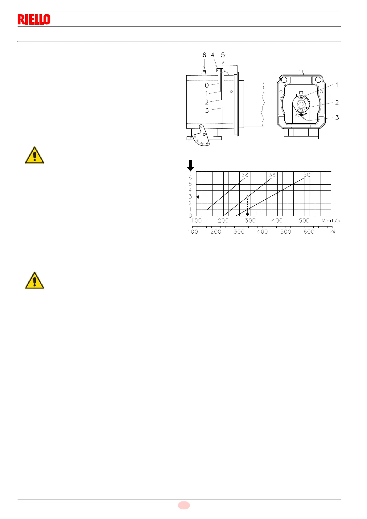
At this point of the installation, the combustion head is fixed to the
boiler as shown in Fig. 11.
It is therefore especially easy to adjust, and this adjustment
depends only on the maximum output of the burner.
2 combustion head adjustments are available:
–air
–gas
In the diagram of Fig. 14, find the notch at which both air and
central gas/air should be adjusted.
Air adjustment
Turn the screw 4)(Fig. 13) until the notch found lines up with
the front surface 5) of the flange.
Gas adjustment
Loosen the screws 1)(Fig. 13) and rotate the ring nut 2) until
the notch you have found corresponds with the indicator 3).
Block the 3 screws 4).
Example:
RS 38 burner output = 337 kW (290 Mcal/h).
The diagram (Fig. 14) shows that the gas and air adjustments for
this output are carried out on notch 3.
The diagram indicates the optimum adjustment for a type of boiler
according to Fig. 3 on page 11.
To facilitate the adjustment, loosen the screw 6)
(Fig. 13), adjust, then block.
The adjustments indicated can be modified during
the initial start-up.
Fig. 14
No. notches
Burner output in 2nd stage
D503
 Loading...