29
20144599
Start-up, calibration and operation of the burner
6.8 Burner operation
6.8.1 Burner start-up
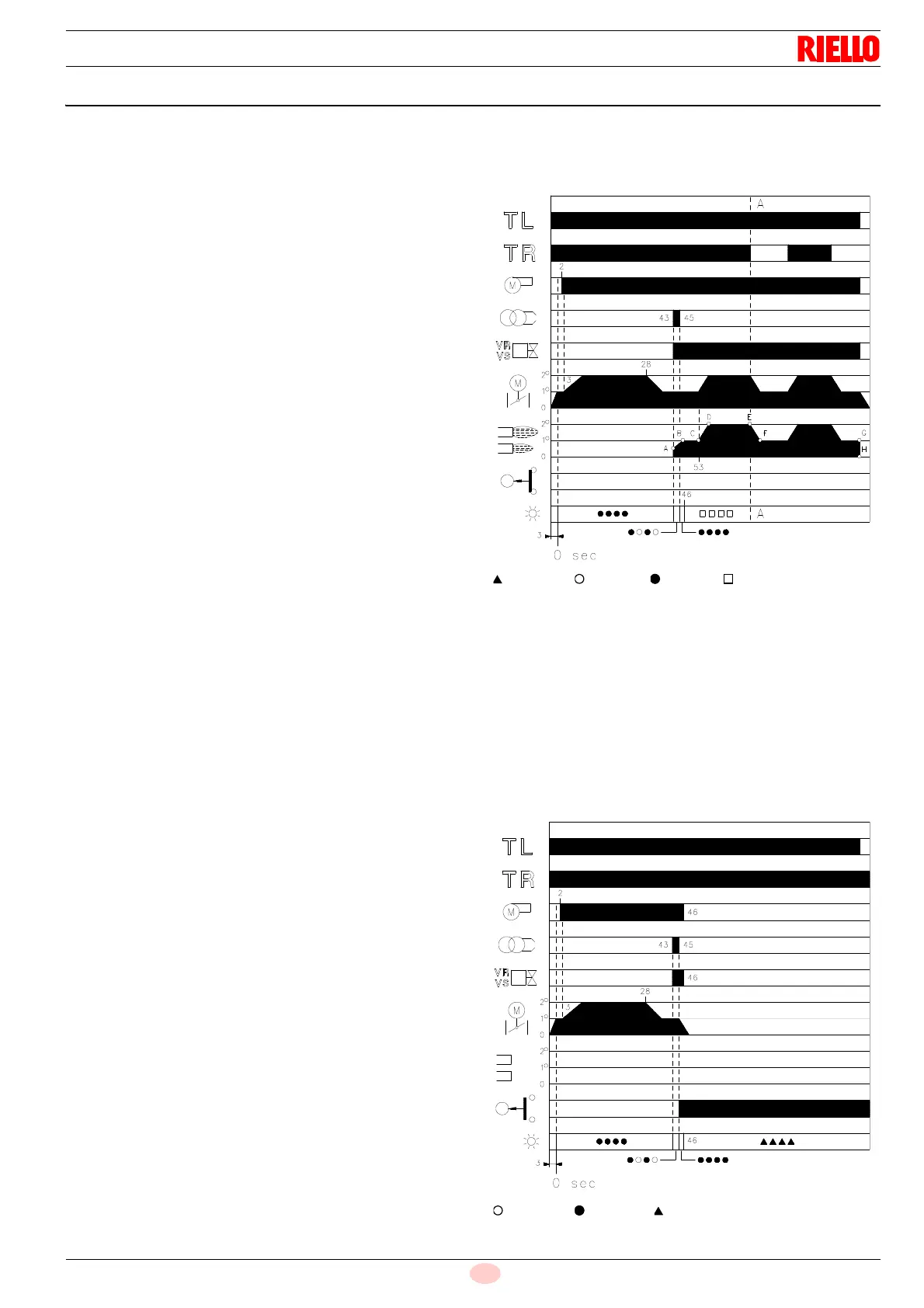
6.8.2 Full-running operation - System equipped
with TR remote control
Once the start-up cycle is completed, the servomotor command
moves on to the TR remote control, that controls the pressure or
temperature in the boiler, point D.
(The control box still continues to check the presence of the flame
and the correct position of the air pressure switch).
• When the temperature or pressure increases and opens the
TR, the servomotor closes the gas butterfly valve and air
damper, and the burner goes from the 2nd to the 1st
operating stage, tract E-F.
• When the temperature or pressure falls and closes the TR,
the servomotor opens the gas butterfly valve and air damper,
and the burner goes from the 1st to the 2nd operating stage.
And so on.
• The burner stops when the heat request is less than the
amount of heat delivered by the burner in the 1st stage, tract
G-H. The TL remote control opens, the servomotor goes
back to angle 0° limited by the cam with light blue lever. The
air damper closes completely to reduce heat losses to a
minimum.
System not equipped with control device TR (jumper wire
installed)
The burner is fired as described above. Then, if the temperature
or pressure increases until the TL opening, the burner shuts
down (tract A-A in the diagram).
* Off Yellow Green Red
For further details see page 30.
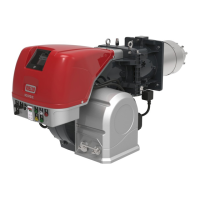
6.8.3 Ignition failure
If the burner does not fire, it goes into lockout within 3 s from
opening of the gas valve and within 49 s from closure of the TL
remote control. The red LED of the control box comes on.
Burner flame goes out during operation
If the flame accidentally goes out during operation, the burner will
go into lockout within 1s.
* Off Yellow Red
For further details see page 30.
Control remote control TL closes.
Servomotor start-up: turn to the right until the angle set
on the cam with the orange lever.
After about 3s:
0 s The control box starting cycle begins.
2 s Fan motor start-up.
3 s Servomotor start-up: turn to the right, until the contact
intervenes on the cam with the red lever.
The air damper is positioned to 2nd stage output.
Pre-purging phase with air flow rate of 2nd stage output.
Duration 25 s.
28 s Servomotor start-up: turn to the left until the angle set on
the cam with the orange lever.
43 s Ignition electrode strikes a spark.
The air damper and gas butterfly valve are in 1st stage
output position.
The safety valve VS opens, along with the adjustment
valve VR, quick opening. The flame ignites with a small
output, point A. The output gradually increases, and the
valve slowly opens, until 1st stage output is reached,
point B.
45 s The spark goes out.
53 s If the TR remote control is closed or replaced by a
jumper, the servomotor goes on rotating until the cam
intervenes with the red lever, bringing the air damper and
gas butterfly valve to the 2nd stage position, tract C-D.
End of control box program.
Fig. 31
D3028
LED
RMG *
STANDARD IGNITION
(no. = seconds from instant 0)
LED
RMG *
Fig. 32
IGNITION FAILURE
D3029