20163082
48
Maintenance
7.2.4 Measuring the ionisation current
The burner is fitted with an ionisation system to check that a
flame is present.
The minimum current for control box operation is 4 µA. The oper-
ator panel displays “30%” (see List of parameters, parameter no.
954).
The burner provides a much higher current, so controls are not
normally required.
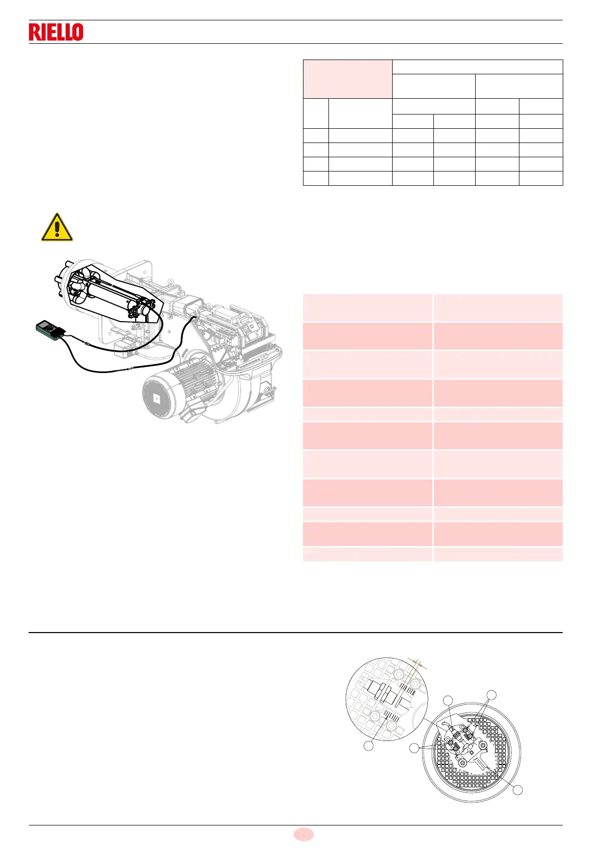
However, if it is necessary to measure the ionisation current, dis-
connect the plug-socket on the ionisation probe cable and insert
a direct current microammeter with a base scale of 100 µA, as
shown in Fig. 34.
Gas leaks
Make sure that there are no gas leaks on the pipes between the
gas meter and the burner.
Gas filter
Replace the gas filter when it is dirty.
Combustion
If the combustion values measured before starting maintenance
do not comply with applicable legislation or do not indicate effi-
cient combustion, consult the Tab. R or contact our Technical
Support Service to implement the necessary adjustments.
It is advisable to set the burner according to the type of gas used
and following the indications in Tab. R.
Tab. R
7.2.5 Safety components
The safety components should be replaced at the end of their life
cycle indicated in the Tab. S.
The specified life cycles do not refer to the warranty terms indi-
cated in the delivery or payment conditions.
Tab. S
7.3 Checking the position of the rpm sensor
To calibrate the rpm sensor, proceed as follows:
loosen the screws 3) rest the sensor on the disc extension 2).
Take the scale 4) as a reference, pull back the rpm sensor by
about a notch so that the distance from the disc extension 2) is
about 2 mm.
Key (Fig. 35)
1 - Rpm sensor
2 - Disc
3 - Screw
4 - Scale
Carefully check the polarities!
EN 676
Air excess
Max. output
1.2
Min. output
1.3
GAS
CO
2
theoretic
al max. 0% O
2
CO
2
% Calibration
CO
NO
X
= 1.2 = 1.3 mg/kWh mg/kWh
G 20 11.7 9.7 9.0 100 170
G 25 11.5 9.5 8.8 100 170
G 30 14.0 11.6 10.7 100 230
G 31 13.7 11.4 10.5 100 230
Safety component Life cycle
Flame control
10 years or 250.000
operation cycles
Flame sensor
10 years or 250.000
operation cycles
Gas valves (solenoid)
10 years or 250.000
operation cycles
Pressure switches
10 years or 250.000
operation cycles
Pressure adjuster 15 years
Servomotor (electronic cam)
10 years or 250.000
operation cycles
Oil valve (solenoid)
10 years or 250.000
operation cycles
Oil regulator
10 years or 250.000
operation cycles
Pipes/ oil fittings (metallic) 10 years
Flexible hoses (if present)
5 years or 30.000
pressurised cycles
Fan impeller 10 years or 500.000 start-ups



 To Next Page