RIGOL
16 DS1000Z-E Quick Guide
horizontal time base.
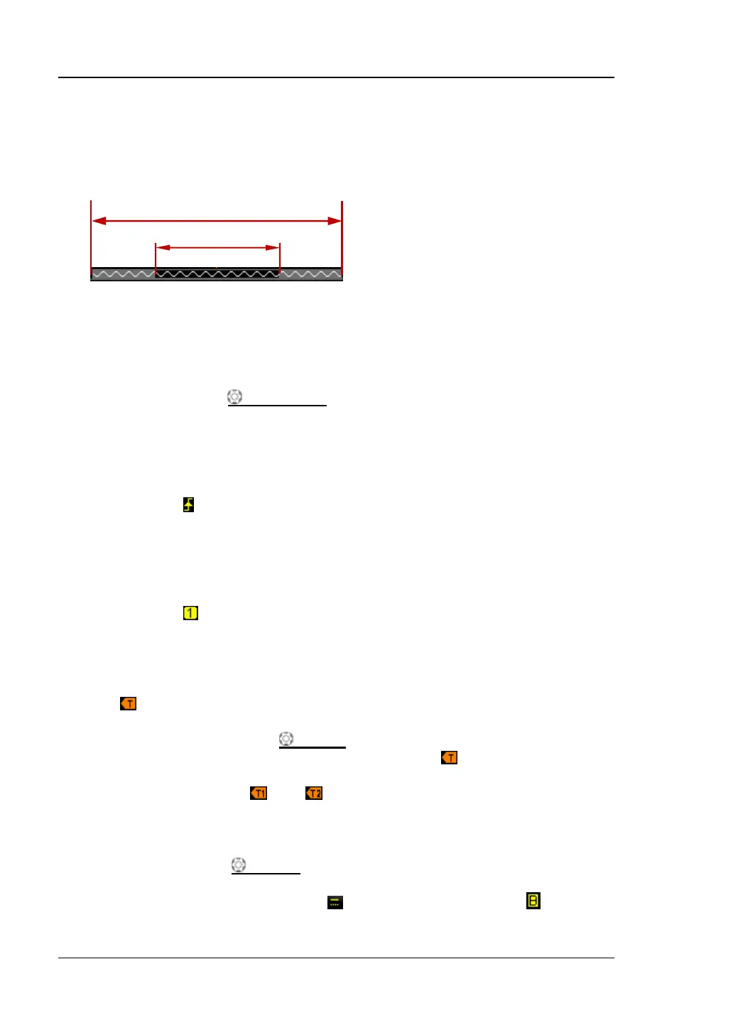
5. Waveform Memory
Provide the schematic diagram of the memory position of the waveform
currently on the screen.
6. Trigger Position
Display the trigger position of the waveform in the waveform memory and on
the screen.
7. Horizontal Position
Use HORIZONTAL POSITION to modify this parameter. Press down the
knob to automatically set the parameter to zero.
8. Trigger Type
Display the currently selected trigger type and trigger condition setting.
Different labels are displayed when different trigger types are selected.
For example: represents triggering on the rising edge in “Edge” trigger.
9. Trigger Source
Display the trigger source currently selected (CH1, CH2, AC Line, or EXT).
Different labels are displayed when different trigger sources are selected and
the color of the trigger parameter area will change accordingly.
For example: denotes that CH1 is selected as the trigger source.
10. Trigger Level
When the trigger source is set to analog channel, you need to set proper
trigger level.
at the right of the screen is the trigger level label and the trigger level
value is displayed at the upper-right corner of the screen.
When using TRIGGER LEVEL to modify the trigger level, the trigger
level value will change with the up and down of .
Note: In slope trigger, runt trigger and windows trigger, there are two
trigger level labels ( and ).
11. CH1 Vertical Scale
Display the voltage value per grid of CH1 waveform vertically.
Use VERTICAL SCALE to modify this parameter.
The following labels will be displayed according to the current channel
setting: channel coupling (e.g. ) and bandwidth limit (e.g. ).