20
2.4 INSTALLATION
2.4.1 SELECTING A LOCATION
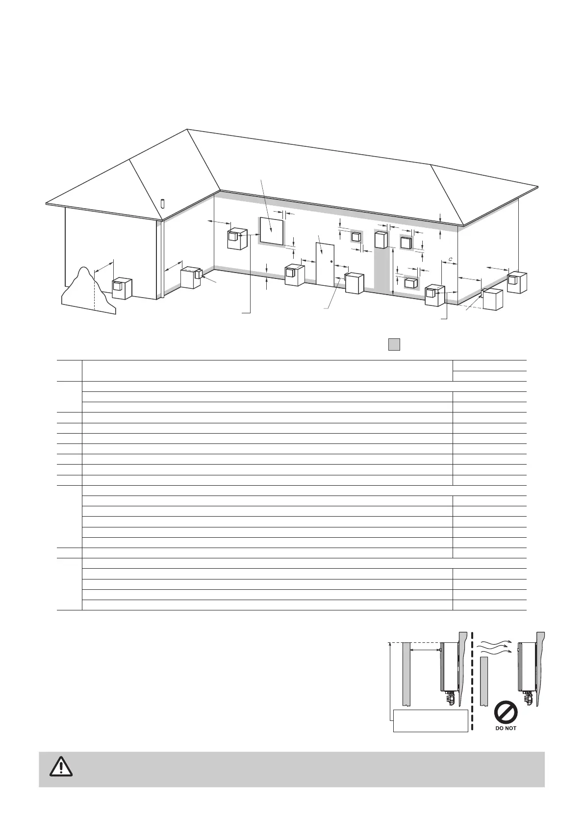
The appliance must be installed at the location in accordance with below diagram.
Horizontal Terminal Clearances
Shading indicates prohibited
area for flue terminals
LEGEND:
I = Mechanical air inlet
S = Structure
M = Gas meter
T = Flue terminal
P = Electricity meter or fuse box
Z = Fan-assisted appliance only
Direction of
discharge
See Note 1
See Note 1
Opening into
a building
T
T
T
T
T
T
T
C
M
d
d
e
e
h
j
j
j
n
b
f
a
h
P
Z
S
k
k
g
g
g
I
T
Door
Ref. Item
Min. Clearances (mm)
Fan assisted
a
Below eaves, balconies and other projections:
For appliances up to 50 MJ/h input 200
For
appliances
over 50 MJ/h input 300
b From the ground, above a balcony or other surface * 300
c Front a return wall or external corner * 300
d From a gas meter (M) (see Note 5) 1000
e From an electricity
meter
or fuse box (P) 500
f From a drain pipe or soil pipe 75
g Horizontally from any building structure* = or obstruction facing a terminal 500
h From any other
flue terminal
, cowl, or combustion air intake * 300
j
Horizontally from an openable window, door, non-mechanical air inlet, or any other opening into a building with the exception of sub-floor ventilation:
Appliances up to 150 MJ/h input * 300
Appliances over 150 MJ/h input up to 200 MJ/h input * 300
Appliances
over 200 MJ/h input up to 250 MJ/h input * 500
Appliances
over 250 MJ/h input * 1500
All fan-assisted flue appliances, in the direction of discharge 1500
k From a mechanical air inlet, including a spa blower 1000
n
Vertically below an openable window, non-mechanical air inlet, or any other opening into a building with the exception of sub-floor ventilation:
Space heaters up to 50 MJ/hr input 150
Other appliances up to 50 MJ/hr input 500
Appliances
over 50 MJ/h input and up to 150 MJ/h input 1000
Appliances
over 150 MJ/h input 1500
* Unless
appliance
is certified for closer installation.
† Prohibited area below electricity meter or fuse box extends to ground level.
Horizontal Obstructions
The appliance must be in an accessible location. Sufficient clearances
shall allow access to, and removal of, all serviceable components.
A minimum horizontal clearance of 600mm between a building structure
and obstruction facing the terminal.
For correct operation of Rinnai external continuous flow water heaters
such a building structure
MUST
‘obstruct’ the full front cover height of the
appliance (appliance dimensions, refer to “Dimensions” section), or extend
vertically above and below the front cover as shown a side.
IMPORTANT
There
MUST
be
NO
partial obstructions to the front cover of the appliance or any other parts of
the appliance casing. This will avoid the appliance failing to operate under windy conditions.
600mm
MINIMUM OBSTRUCTION
HEIGHT IS TO BE NO LESS
THAN TOP OF APPLIANCE