Continuous ow internal ueing guide: 11748-D 04-13 | 5
Flue gases can reach temperatures up to 200 °C. The flue
terminal is to terminate in a location so as not to cause a
nuisance, in accordance with AS/NZS 5601.
Flueing guidelines
Flue support
Ensure the flue is fully
supported independently of
the appliance by use of suitable
clips or brackets, in accordance
with AS/NZS 5601. Appropriate
standoff brackets are supplied
with each FFSSROOFCOWL and
FFSSPIPE1000.
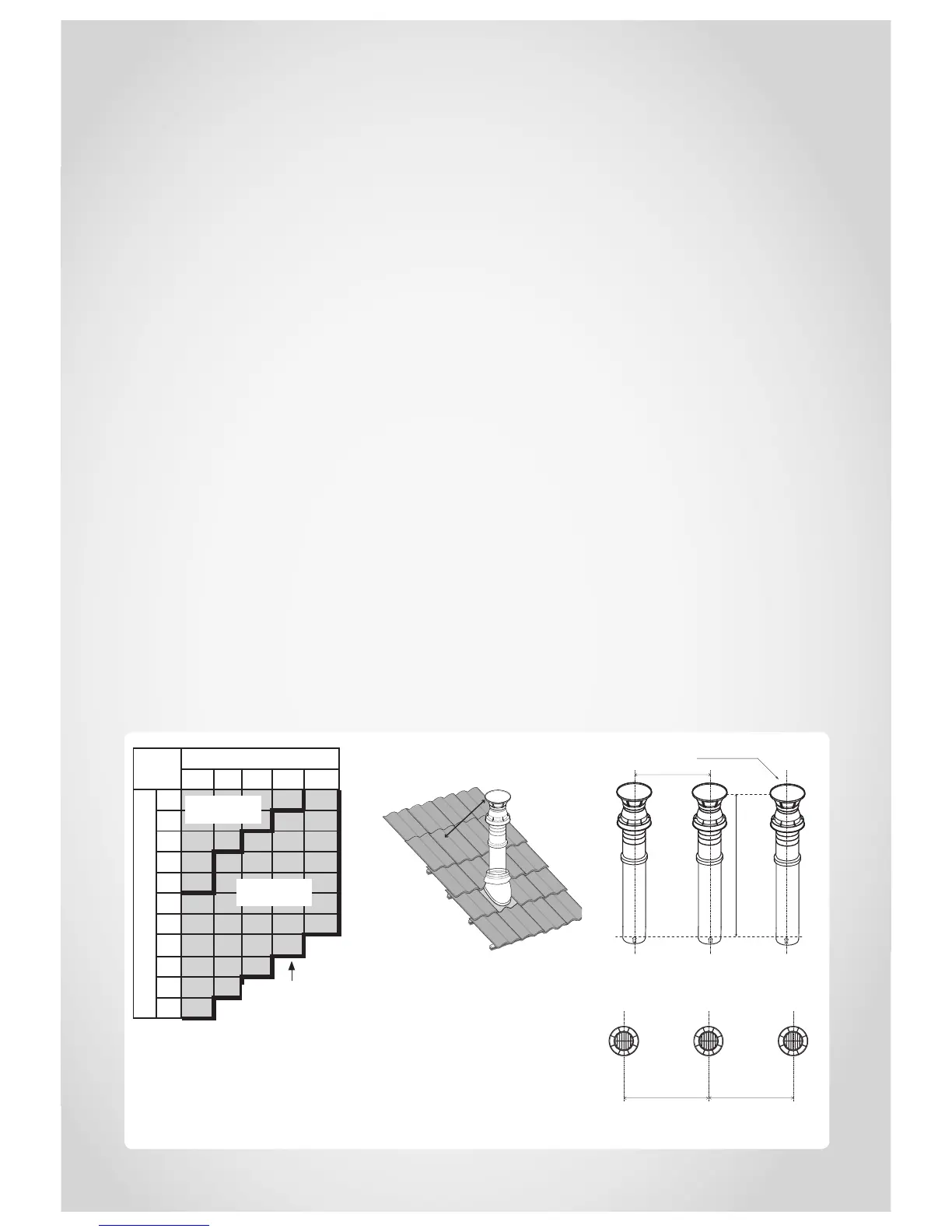
Flue length
The chart highlights the
maximum flue length and
number of bends. It also shows
the difference between a short
and long flue.
For flues over 2 m there is a
DIP switch change required—
refer commissioning checklist
supplied with the appliance.
This increases the combustion
speed to overcome the
additional friction loses.
Vertical terminations.
To ensure products of
combustion are cleared,
adequate clearance from the
building is required.
The flue cowl should have a
500 mm clearance from any
part of the building. This also
applies to steeped and pitched
roofs, which should be clear of
the ridge line.
Lesser clearances may provide
perfectly adequate flue systems
depending on the installation.
Minimum clearances are shown
in AS/NZS 5601.
Multiple flues
Ensure minimum distances, as
shown are maintained.
Each terminal is to be
terminated at the same vertical
height.
Number of 90 ° Bends
0 1 2 3 4
Flue Length (m)
1
2
3
4
5
6
7
9
11
13
15
Short flue
setting
Long flue
setting
Max. flue length
Min. clearance 500 mm to
nearest part of roof
Min. 350 mm
Min. clearance 500 mm
Roof cowl
Min. 350 mm Min. 350 mm
Flue length table
Vertical terminal clearance
Multiple flues - vertical flue clearance
Multiple flues - horizontal flue
clearance