Infinity REU-V3232W /HD250E REU-V3232WC - 31 - Issue 1 - 8/09/03 ©Rinnai
9. Water Flow Servo Circuit
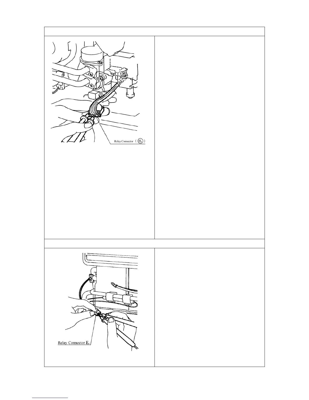
a.) Disconnect relay connector (B
2
), and
measure resistance between Red and Blue of
Water Flow Servo.
Normal: 10~30
Ω
If normal, proceed to b.
Faulty: Replace Water Flow Servo and
Water Flow Sensor.
b.) Disconnect relay connector (B
2
), and
measure voltage between Orange (+) and
Grey (-) on PCB unit side.
Normal: DC11~13V
If normal: proceed to
c.
Faulty: Replace PCB unit.
c.) Measure voltage between Brown and Grey
with relay connector (B
2
) connected (with no
water flowing, water flow servo fully open).
Normal: DC4~6V
Faulty: Replace Water Flow Servo with
Water Flow Servo.
d.) Measure voltage between Yellow and Grey
with relay connector (B
2
) connected (with no
water flowing, water flow servo fully open).
Normal: < DC1.0V
Faulty: Replace Water Flow Servo and
Water Flow Sensor.
10.Heat Exchanger Outlet Thermistor Circuit
Check Heat Exchanger Outlet Thermistor if
error indicator “33” is displayed.
Disconnect relay connector (E
2
) and measure
resistance between White and White.
Circuit Break: Resistance > 1M
Ω
Short circuit: Resistance < 1Ω
If normal, proceed to Water Flow Servo
Circuit
If faulty, replace Heat Exchanger Outlet
Thermistor.
Note: For controller readout of thermistor
temperature whilst operational refer
maintenance monitor (chapter 17) No. 11.
 Loading...