Infinity REU-V3232W /HD250E REU-V3232WC - 26 - Issue 1 - 8/09/03 ©Rinnai
16. Component and Circuit Checks
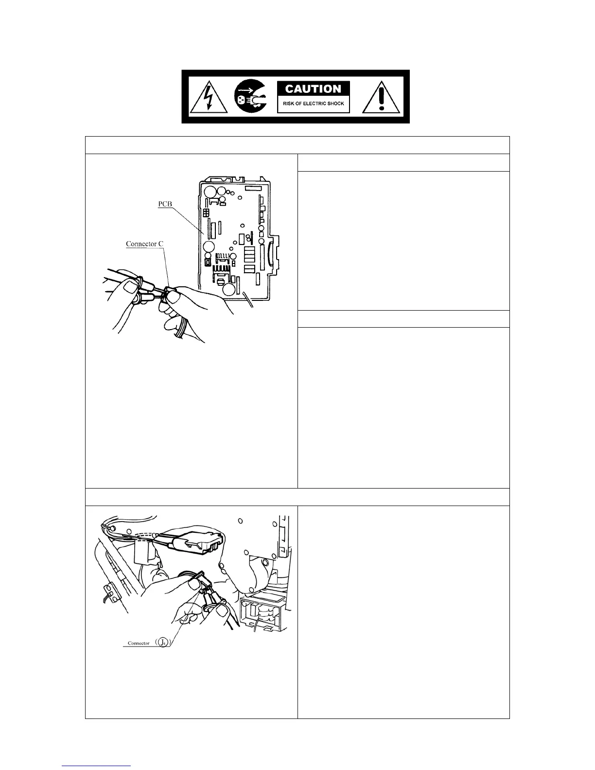
1. Combustion Fan Circuit
Check the Motor
Check the combustion fan if the error indicator
displays “61”.
Measure voltages between Black and Red of the
PCB connector (C).
Normal: DC7~45V (when fan ON)
DC0V (when fan OFF)
If normal proceed to check the rotation
sensor
Faulty: Replace PCB
Check for the Fan Rotation Sensor
a.) Measure voltages between Black and Yellow
of connector (C).
Normal: DC10~14V
If normal, proceed to
b.
Faulty: Replace PCB.
b.) Measure voltages between Black and White
of connector (C).
Normal: DC2~9V
If normal, proceed to Sparker Circuit 2.
Faulty: Replace Combustion Fan.
2. Sparker Circuit
a.) Measure voltage between Grey and Black of
connector (J
6
).
Normal: AC90~110V
If normal, proceed to
b.
Faulty: Replace PCB.
b.) Disconnect connector (J
6
) and measure
resistance between both terminals of the
sparker.
Normal: > 1M
Ω
If not sparking, adjust or replace ignition
plug.
Faulty: Replace Sparker.
 Loading...