Infinity REU-V3232W /HD250E REU-V3232WC - 27 - Issue 1 - 8/09/03 ©Rinnai
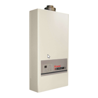
3a.Main Solenoid Valve (SV
0
) Circuit
Check the main solenoid if error indicator “11”
is displayed.
a.) Disconnect Main Solenoid connector and
measure resistance between Pink and Black.
Normal: 1.5~1.9k
Ω
If normal, proceed to b.
Faulty: Replace Main Solenoid.
b.) Measure voltage between Pink-Black of
Main Solenoid connector.
Normal: DC80~100V
If normal, proceed to Solenoid Valve SV
1
Faulty: Replace PCB.
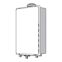
3b.Solenoid Valve 1 (SV
1
) Circuit
Check Solenoid 1 if error indicator “11” is
displayed.
a.) Disconnect Solenoid 1 connector and
measure resistance between Red and Black.
Normal: 1.8~2.2k
Ω
If normal, proceed to b.
Faulty: Replace Solenoid 1.
b.) Measure voltage between Red and Black of
Solenoid 1 connector.
Normal: DC80~100V
If normal, proceed to Solenoid Valve 2
(SV
2
) Circuit
Faulty: Replace PCB.
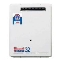
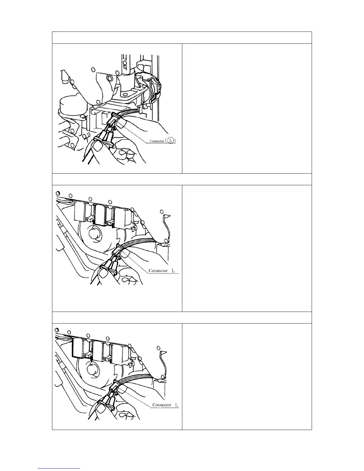
3c. Solenoid Valve 2 (SV
2
) Circuit
a.) Disconnect Solenoid Valve 2 connector and
measure resistance between Orange and
Black.
Normal: 1.8~2.2k
Ω
If normal,, proceed to b.
Faulty: Replace Solenoid Valve 2.
b.) Measure voltage between Orange and Black
of Solenoid Valve connector.
Normal: DC80~100V
If normal, proceed to Thermal fuse Circuit.
Faulty: Replace PCB.
 Loading...