Infinity REU-V3232W /HD250E REU-V3232WC - 28 - Issue 1 - 8/09/03 ©Rinnai
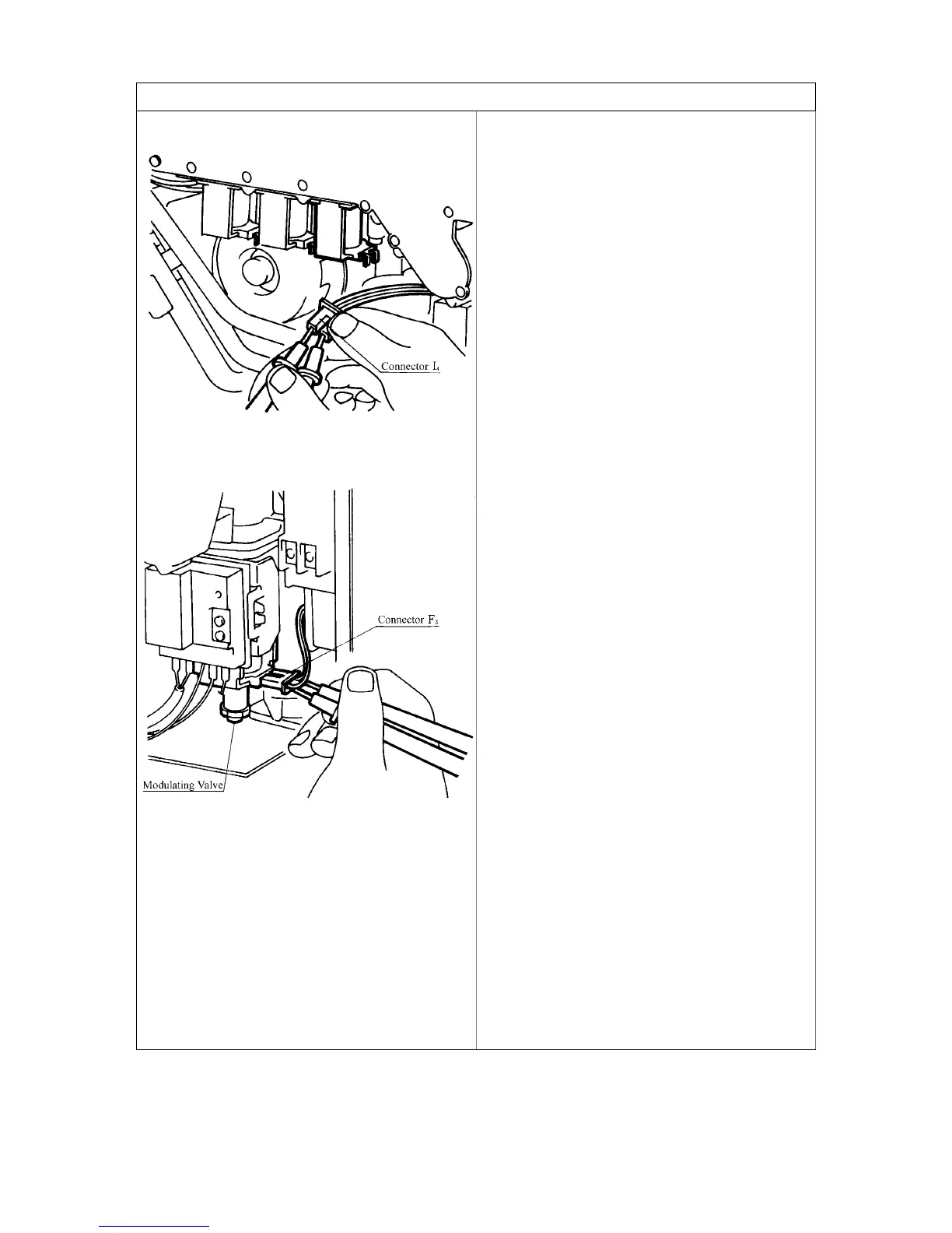
3d.Valve Circuit
a.) Disconnect Solenoid connector, measure
resistance between Yellow and Black.
Normal: 1.8~2.2k
Ω
If normal, proceed to b.
Faulty: Replace Solenoid Valve 3.
b.) Measure voltage between Yellow and Black
of SV
3
connector.
Normal: DC80~100V
If normal, proceed to Modulating valve
circuit.
Faulty: Replace PCB.
c.) Disconnect Modulating Valve fasten
terminal and measure resistance between
terminals.
Normal: 70~90
Ω
If normal, proceed to b.
Faulty: Replace Modulating Valve.
d.) Measure voltage between Orange and
Orange of Modulating Valve fasten terminal.
Normal: DC1.0~25V
If normal, proceed to
c.
Faulty: Replace PCB.
e.) Check the gas secondary pressure change
when set temperature on the remote control
changes from 37 to 55
o
C.
Normal: If secondary pressure changes, go
to Water Flow Servo Circuit.
Faulty: Replace Modulating Valve.
 Loading...