Linear ue installation guide 13541-A 01-20 | 15
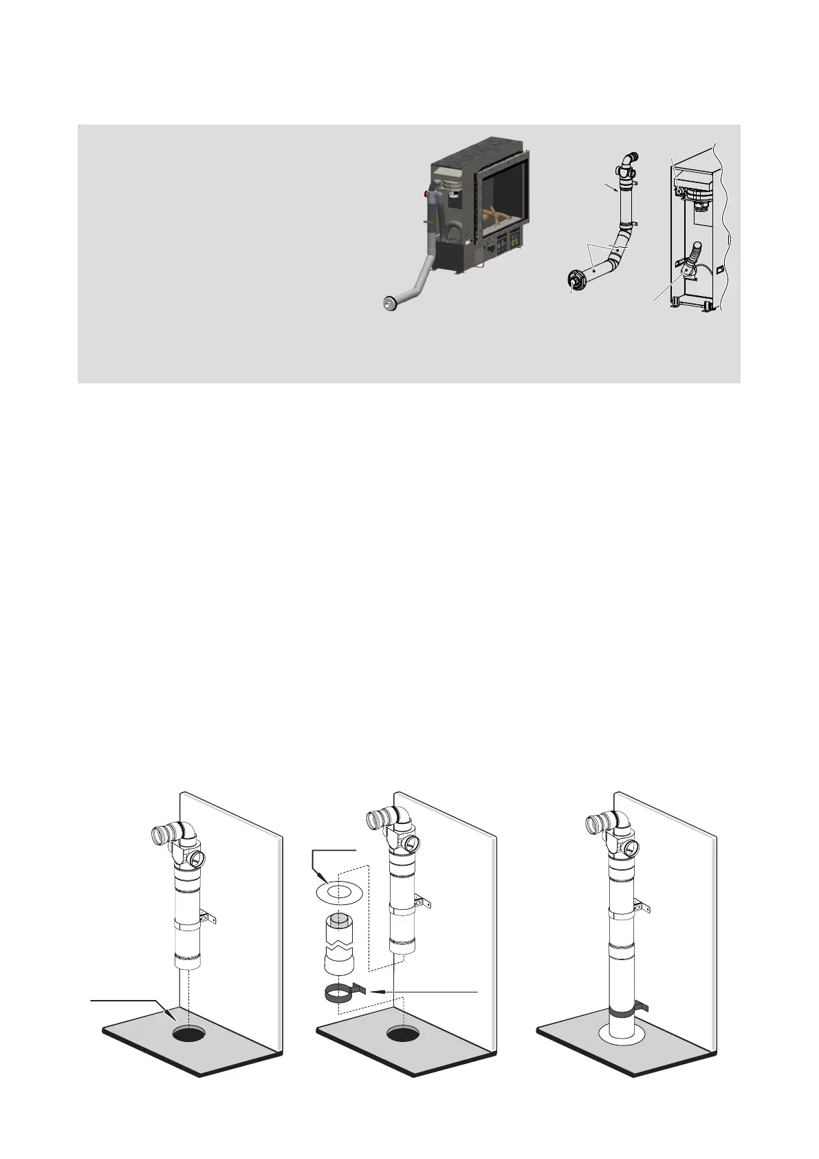
Down and out ue assembly
I
n
t
e
r
i
o
r
wa
l
l
I
n
te
ri
o
r
wa
l
l
Wall plate
Stand off clip
I
n
t
e
r
i
o
r
w
a
l
l
Floor penetration
Air inlet pipe
Flue exhaust
outlet
ESWTERM
ESPIPE900
LSFKIT01
The down and out ue allows for
the adaption ue component to face
downwards, and for the ue to run
vertically through a hole in the oor, and
then terminate horizontally outside—ue
must terminate 300 mm above the ground.
With the Linear installed into the support framing:
1. Fit the ue components and lengths of ue pipe as required. Ensure the ue transition
section of the LSFKIT01 is included. NEVER discard this section as this will cause an unsafe
installation due to a buildup of heat in the ue.
2. The ue penetration should be made at the same time as the cutout for the gas connection.
The oor penetration minimum diameter is 80 mm to non-combustible surfaces such as brick,
and 100 mm to combustible surfaces such as plaster.
3. Pass the ue pipe through the internal wall plate and through the oor penetration, and secure
the wall plate in place to seal the oor.
4. Prepare the horizontal section of the ue system under the oor by connecting the ue pipe
and bends as required. Allow for a 2° continuous fall from the rst section of the horizontal ue
pipe to the wall penetration.
5. Create the wall terminal, refer p.17, ensuring a 300 mm clearance between the ue terminal
and ground level.
A minimum of 300 mm of straight ue before any bends. This is required due to the heat
produced from the initial section of ue, which could melt the outer plastic. The LSFKIT01 has
the 300 mm min. ue length built in.
 Loading...