Rinnai Australia - 30 - Solar Split Systems Operating / Installation Manual Version 8 - 18/10/10
OVERVIEW OF SYSTEM COMPONENTS
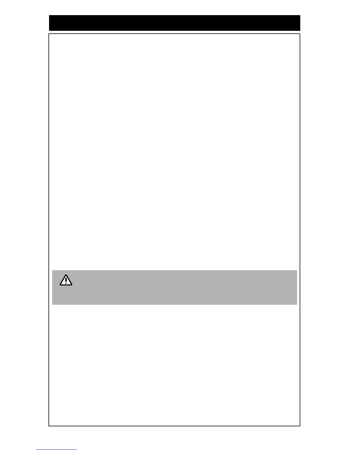
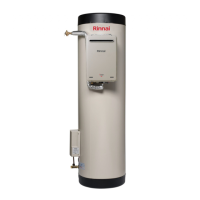
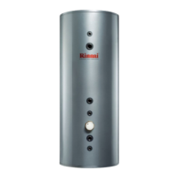
The range of gas boosted solar hot water systems include all the components shown in Figure 32
- 41 (refer to the appropriate Figure depending on cylinder type/size and kit on the following
pages).
The pump kit and associated plumbing connections are factory pre-assembled. All other
components and fittings will require connection on site. The gas booster and pump/controller kit may
be mounted to the front of the storage cylinder casing or in an alternative external location. In all
cases the heated outlet of the cylinder is connected to the cold water inlet of the gas booster.
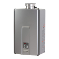
GAS BOOSTER LOCATION
The gas booster is designed for ‘Outdoor” Installation only. As such, it must be located in an above
ground open air situation with natural ventilation, without stagnant areas, where gas leakage and
products of combustion are rapidly dispersed by wind and natural convection. The location must
comply with the clearances specified in AS5601.
The gas booster must be mounted on a vertical structure with the water and gas connections on the
underside pointing downwards. In most installations the gas booster is mounted directly on the
storage cylinder using two custom made mounting brackets. In all cases the heated outlet of the
cylinder is connected to cold water inlet of the gas booster.
GAS SUPPLY
The maximum gas consumption of the gas booster and the required gas pressure are shown on the
appliance data plate. If the gas pipe sizing is insufficient the customer will not get the full
performance benefit. Gas pipe sizing must consider the gas input to the gas booster as well as all
the other gas appliances on the premises. The gas meter and regulator must be specified for this
gas rate. An approved sizing chart such as the one in AS 5601 should be used. An approved full
flow isolation valve and disconnection union must be fitted to the gas supply inlet of the gas booster.
Isolation valves must not be fitted directly.
HOT WATER DELIVERY TEMPERATURE
Gas boosters for use in solar hot water systems are preset to deliver a fixed temperature of 60°C in
accordance with plumbing regulations. In addition, they contain the warning stating "Rinnai Water
Controllers are NOT compatible with solar hot water installations and MUST NOT BE USED" in the
vicinity of the temperature controller connections inside the appliance.
Gas Boosters other than models designated “S20”, “S26” or “Solar” must not be
used.
Gas Boosters marked with the text: "THIS APPLIANCE DELIVERS WATER NOT
EXCEEDING 50°C IN ACCORDANCE WITH AS 3498" are incompatible with solar hot
water systems and must not be used.