Rinnai Australia - 46 - Solar Split Systems Operating / Installation Manual - Version 8 18/10/10
ADJUSTING FLOW CONTROL VALVE
The purpose of the flow control valve is to allow the water flow
rate through the collector collectors and storage cylinder to be
controlled to optimise the performance of the system. The
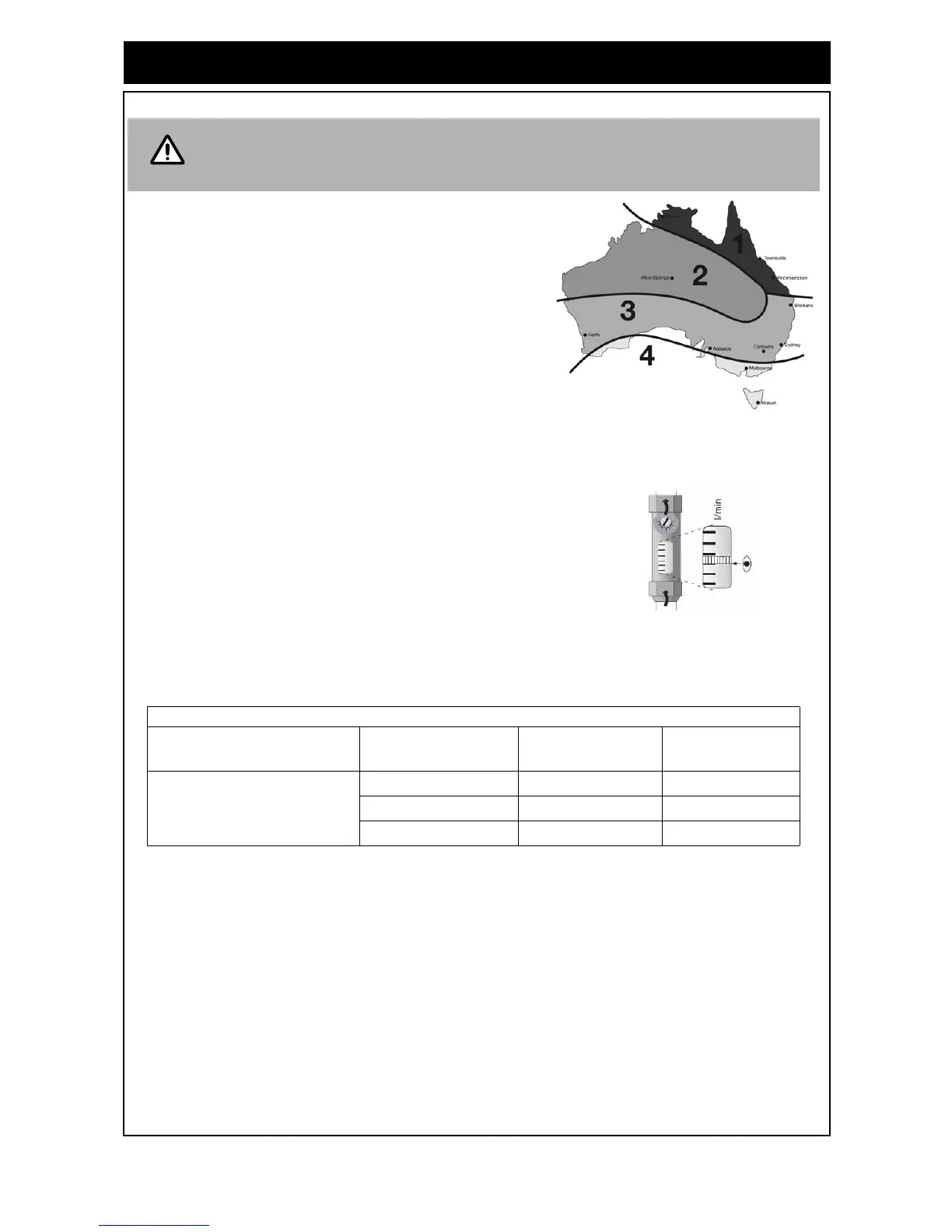
optimum flow rate for the system will depend on the type of
system (electric or gas boost), the number of collector
collectors, and the location of the installation (see the solar
zone shown in Figure 38).
Figure 38 - Australian Solar Zones
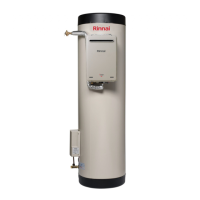
The flow control valve needs to be adjusted while the pump is
operating. The flow rate valve is read at the bottom of the baffle
float as shown in Figure 39 Using a flat bladed screw driver
turn the screw on the valve until the value from Table 10 is
achieved.
Figure 39 - Adjusting Flow Control Valve
The installer will need to set the flow rate to the value shown in Table 9 below.
PRE SOLAR HEATING CHECKS
Before commencing solar heating of the water in the system ensure the following actions have been
completed:
Solar Collectors
1. Are the solar collectors installed with the correct slope and orientation to the sun?
2. Is the installation finished neatly with the roof made good, all tiles and flashings in place?
3. Are the bolts tight on the roof framework?
4. Are all solar collector straps fitted and correctly anchored to the roof structure?
5. If leak testing completed and successful, have any covers been removed from the solar collectors?
6. Has operation of the solar pump been checked?
7. Have the hot and cold sensors and leads been positioned and connected correctly?
If the solar pump does not activate the system can still be commissioned as detailed in
these instructions, but solar preheating will not be available until the pump and
controller operate.
Table 10 - Optimum Flow Rate (Litres/min).
No. of Collectors
Zones
1, 2 & 3
Zone 4
Gas Boosted
1 0.50 0.50
2 1.25 1.25
3 2.10 2.10