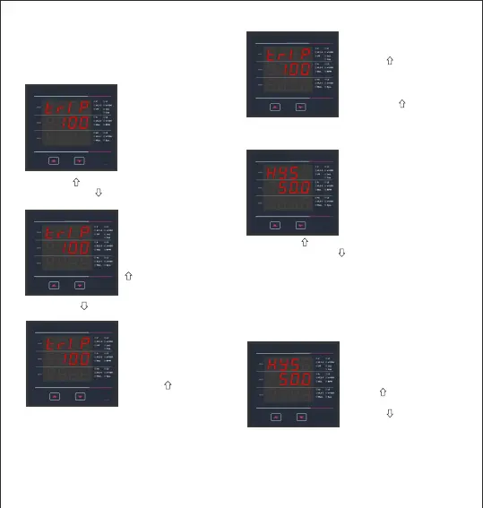
3.2.4.1.1.1.3 Trip Point Selection
V
A
V
A
r h
K
V
DM
A h
SY
This screen applies to the Trip Point Selection.
This screen allows the user to set Trip point for
the meter.
The first digit entered,
prompt for second digit
(Blinking digit denotes
that value will be
changing).Use the
“ ” key to scroll the
value of the second digit.
V
A
V
A
K
r h
K
M
L1
L2
DM
L3
A h
SY
Press the “ ” key to advance to next digit.
V
A
V
A
K
L2 M L3 W Ø
r h
K
V
L1
L2
DM
L3
A h
SY
The second digit entered,
prompt for third digit
(Blinking
digit denotes that value
will be changing).
Use the “ ” key to scroll
the value of the third digit.
The allowable range
for High Alarm and
Low Alarm can be
referred from table 2.
Enter value, prompt
for first digit. (Blinking
digit denotes that value
will be changing).
Press the “ ” key to scroll the values of the first
digit. Press the “ ” key to advance to next digit.
17
Entered the value for third
digit.
Press the “ ” key to advance
to next Screen
“Hysteresis selection”
(see section 3.2.4.1.1.1.4)
Pressing the “ ” key will
return in edit mode.
V
P
Sys
V
A
K
r h
K
V
L1
L2
DM
L3
A h
SY
Note : In case of lo alarm if trip point is set at 100%
then maximum 20% Hysterisis can be set.
Press the “ ” key to scroll the value of the
first digit Press the “ ” key to advance to next digit.
Hysteresis for Frequency is calculated as % of trip
point span from 40Hz. e.g. If trip point is 50%(55Hz)
and hysteresis is set to 10%, then relay will reset at
53.5Hz [10% of (55 - 40Hz) 15Hz is 1.5Hz. Hence,
55 -1.5= 53.5Hz
3.2.4.1.1.1.4 Hysteresis selection
This screen applies to the Hysteresis selection.
This screen allows the user
to set Hysteresis for relay
output
The allowable range is
0.5% to 50 % of Trip point.
Enter value, prompt for first
digit. (Blinking digit denotes
that value will be changing
The first digit entered, prompt
for second digit Blinking digit
denotes that value
will be changing).
Use the “ ” key to scroll the
value of the second digit.
Press the “ ” key to
advance to next digit