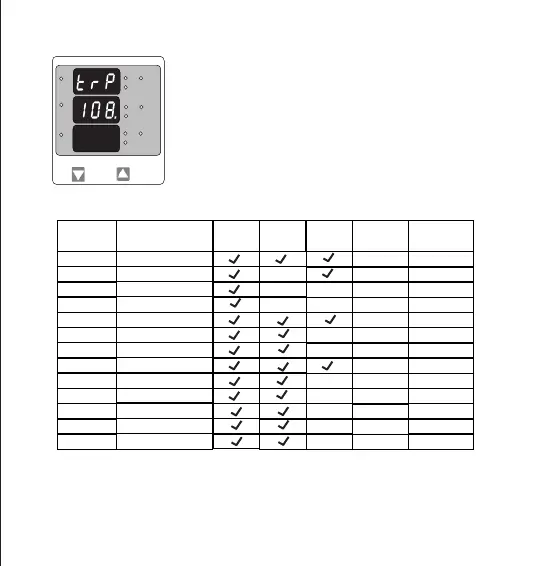
Trip point selection
This screen will not appear if parameter None (00) is Selected in previous
menu. The trip point can be set as % of the Nominal value of
selected parameter (Refer Table 2).
Pressing “DOWN” key will enter trip point edit screen.
Pressing “UP” key will set displayed value as trip point and exit set up.
Further Functionality is same as Potential Transformer Secondary value
(see section 3.2.4)
TABLE 2 : Parameters for limit monitoring
Parameter
00
01
02
03
04
05
06
07
10
11
12
13
14
No.
3P4W
3P3W
1P2W
Trip point
—
X
X
X
X
X
X
X
X
X
X
X
X
10 - 120%
10 - 120%
10 - 120%
10 - 120%
10 - 120%
10 - 120%
10 - 100%
10 - 120%
10 - 120%
10 - 120%
10 - 120%
10 - 120%
Measured Parameters
None
Voltage L1
Voltage L2
Voltage L3
Current L1
Frequency
Voltage VL1-L2
Current L2
Current L3
Voltage VL2-L3
Voltage VL3-L1
System Current
System Voltage
Set range
Vnom (L-N)
100%
—
Inom
Inom
Inom
(1)
66Hz
Vn (L-L)
Vn (L-L)
Vn (L-L)
(2)
Vnom
Inom
Value
Vnom (L-N)
Vnom (L-N)
Note : (1) For Frequency 10% corresponds to 45Hz and 100% corresponds to 66Hz.
(2) For 3P 4wire and 1ph the nominal value is V and that for 3P3W is V .
L-N L-L
(3) Nominal Value is to be considered with set CT/ PT Primary values.
(4) For single phase L1 Phase values are to be considered as System values.
*
L3-L1
L2-L3
Hz
x1000
L1-L2
Volt
x1000
L3
L1
L2
A
x1000
18