L N
AUX
SUPPLY
L
N
2
11
1
3
13
14
P1
S1
L
O
A
D
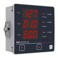
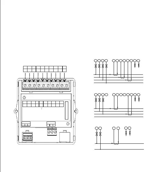
Multifunction Meter (3o)
13
AUX.
IL1
IL2
IL3
VL1
VL2
VL3
IL1’
IL2’
IL3’
N
1
2
3
4
5
6
7
8
9
11
IL1 IL2
IL3
VL1 VL2
VL3
IL1’
IL2’
IL3’
N
1
2
3
4
5
6
7
8
9
11
MODEL : OPTIMA VAF
INPUT :500VL-L, 5A/1A, 45-65Hz
AUX SUPPLY :40V-300V AC-DC , 3VA
SR NO : 14/02/3232
ORDER CODE : RISH OPTIMA VAF - 3L- EA - L
+.
-.
~.
~.
14
LIMIT SW.
COM NO
NC
4.5 Fusing
4.6 Earth/Ground Connections
It is recommended that all voltage lines are tted with 1 amp HRC fuse.
For safety reasons, CT secondary connections should be grounded in accordance with local
regulations.
5. Connection Diagrams
L N
AUX
SUPPLY
L1
L2
2
5
8
11 1
3
4
6
7
9
13
14
P1
S1
S1
P1
P1
S1
L
O
A
L3
N
D
L N
AUX
SUPPLY
L1
L2
2
5
8
11 1
3
4
6
7
9
13
14
P1
S1
P1
S1
L
O
A
L3
N
D
3-PHASE 4-WIRE UNBALANCED LOAD
3-PHASE 3-WIRE UNBALANCED LOAD
SINGLE PHASE 2-WIRE
22