PG
1
8
PG
17
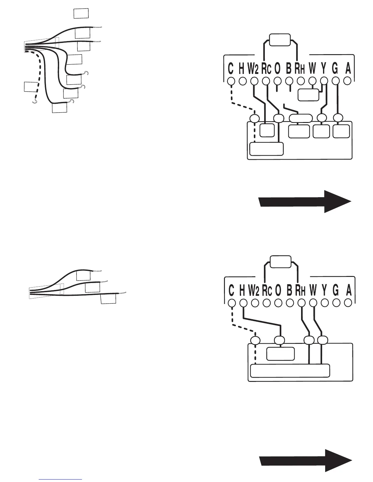
STEP 1 - Connect the G wire to
the G terminal on the thermostat.
This connects the Fan.
STEP 2 - Add a jumper wire
between W and Y.
STEP 3 - Connect the Y wire to
the Y terminal on the thermostat.
This connects the Compressor.
STEP 4 - Connect the O or B wire to the
O or B terminal on the thermostat. (If you have both O
and B wires, use the O and tape off the B).
This connects the change over valve.
STEP 5 - Connect the R wire to the RC terminal on
the Thermostat. This connects to the 24vac power.
STEP 6 - Connect W or W2 to W2 on the thermostat. This connects the AUX heat.
Your HVAC system is now connected to the thermostat.
Return To Page 9
HEAT PUMP
with Auxillary Heat
STE
P 1
- Connect the H wire to th
e H termin
al on
the the
rmostat.
This con
nects the
Humidifier.
STEP
2 - Connect the W wire to
the W te
rminal on
the
thermostat. T
his connects the Heat control line.
STEP
3 - Connect the R wire to the RH terminal on
the th
ermostat.
This connects the Heater Power.
Your Hu
midifier a
nd he
ater a
re now co
nnecte
d to the thermostat.
Re
tu
rn To
Pag
e 9
O or B
(not both)
HEAT PUMP
Change
Ov
er
AUX
Heat
G
O or B
R
C
FAN
Y
Comp
24VAC
Power
jumper
wire
jumper
wire
Thermostat
Humid
ifie
r
H
R
W
C
2
4V
A
C
Po
wer
jump
er
wir
e
Th
e
rmo
st
a
t
NOTE: Wires marked with the dotted line are optional.
For your Remote Control to operate you must connect the C wire.
NOTE
: Wires marked w
i
th the d
otted l
ine are opti
o
nal
.
F
or your Remote Control to o
per
ate
you must connect the C wire.
W
RH
H
Exte
rn
a
l
H
u
m
i
d
i
fi
e
r
w
/ a
ny H
e
a
te
r
B
G
Y
R
C
Fro
m hea
t pump
with
Au
x hea
t
O
or
W
or
W2
 Loading...