PG
16
PG 15
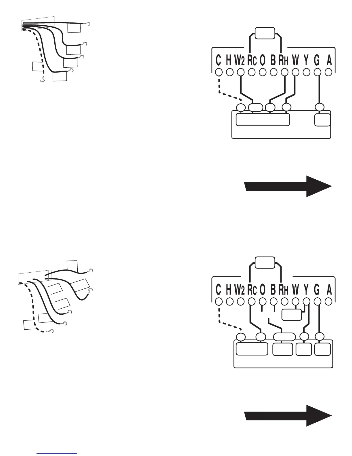
STEP 1 - Connect the G wire to
the G terminal on the thermostat.
This connects the Fan.
STEP 2 - Add a jumper wire
between W and Y.
STEP 3 - Connect the Y wire to
the Y terminal on the thermostat.
This connects the Compressor.
STEP 4 - Connect the O or B wire
to the O or B terminal on the
thermostat. (If you have both O and B contact
Ritetemp or your local HVAC contractor for further
help) This connects the change over valve.
STEP 5 - Connect the R wire to the RC terminal on the Thermostat.
This connects to the 24vac power.
Your HVAC system is now connected to the thermostat.
Return To Page 9
HEAT PUMP
w/o Auxillary Heat
From Fur
nace
and
A
C unit
R
G
Y
C
O
or
B
O or B
Single Stage HEAT PUMP
Change
Over
G
O or B
R
C
FAN
Y
Comp
24VAC
Power
jumper
wire
jumper
wire
Thermostat
STEP 1 - Connect the G wire to
the G terminal on the thermostat.
This connects the Fan.
STEP 2 - Connect the
between W wire to W. This
connects the 1st stage heat.
STEP 3 - Connect the between
W2 wire to W2. This connects the
2nd stage heat.
STEP 4 - Connect the R wire to the RH terminal on
the Thermostat. This connects to the 24vac power.
Your HVAC system is now connected to the thermostat.
(If the system also has AC, connect it per instructions for RC and Y on pg 14)
Return To Page 9
NORMAL 2 Stage
Heat System
Two Stage Heat System
G
RW2
C
FAN
W
Two Stage
Furnace
jumper
wire
Thermostat
NOTE: Wires marked with the dotted line are optional.
For your Remote Control to operate you must connect
the C wire.
NOTE: Wires marked with the dotted line are optional.
For your Remote Control to operate you must connect
the C wire.
W
G
W2
R
C
Fro
m No
rmal
two sta
ge
sy
ste
m
 Loading...