PG 14
PG 13
From Fur
nace
and
A
C unit
G
W
Y
RH
RC
C
R
G
Y
W
C
RH
or
Fr
o
m
Furnace
and AC un
i
t
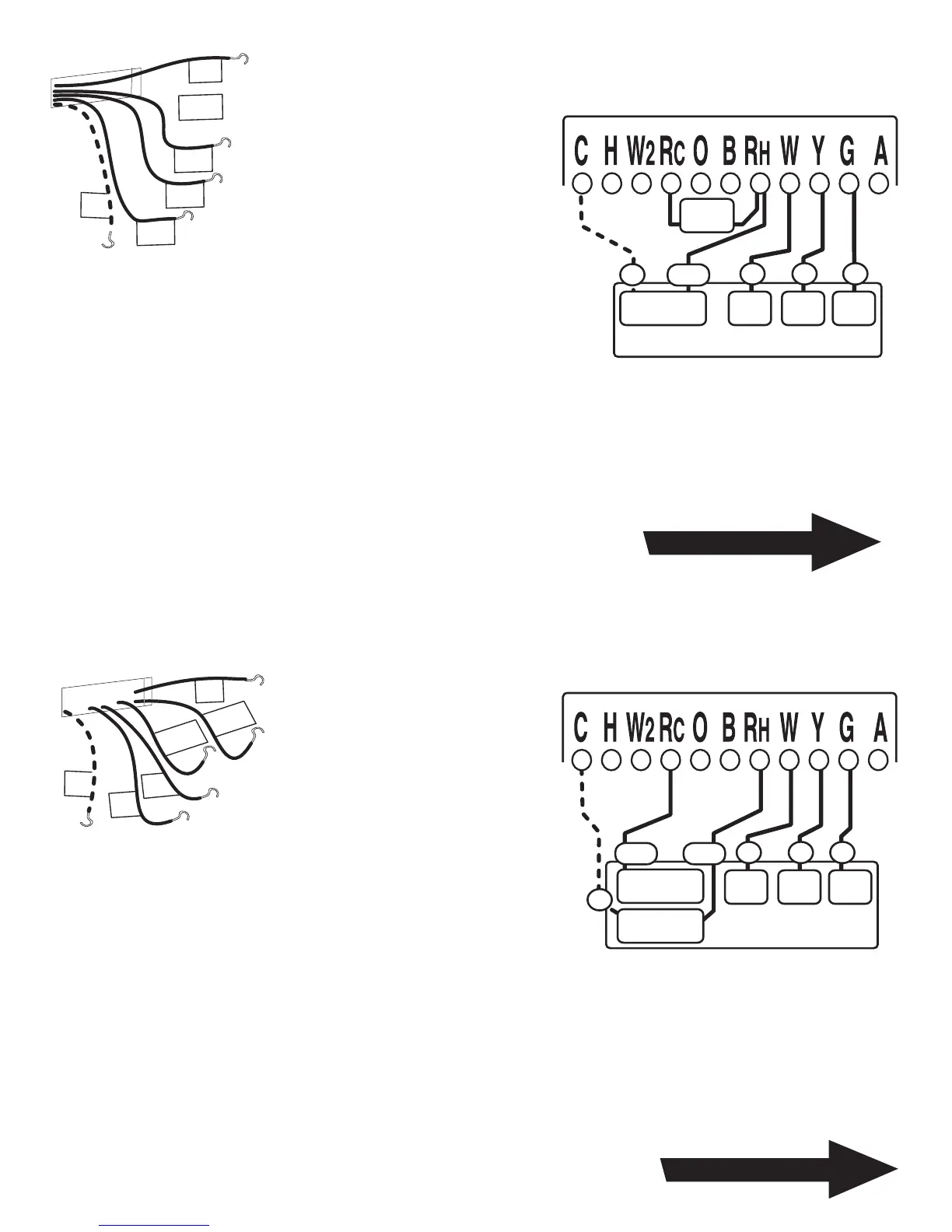
STEP 1 - Connect the Y wire to
the Y terminal on the thermostat.
This connects to the Cooler
compressor.
STEP 2 - Connect the RH or R
wire to the RH terminal on the
thermostat.
This connects the Heater/Cooler
Power.
STEP 3 - Connect the W wire to the W
terminal on the thermostat.
This connects to the heater control line.
STEP 4 - Connect the G wire to the G terminal on the Thermostat.
This connects to the Fan.
Your HVAC system is now connected to the thermostat.
STEP 1 - Remove the Jumper wire.
STEP 2 - Connect the Y
wire to the Y terminal on the
thermostat. This connects to
the Cooler compressor.
STEP 3 - Connect the RH wire to the RH
terminal on the thermostat. This connects to the
Heater Power .
STEP 4 - Connect the RC wire to the RC terminal
on the thermostat. This connects to the Cooling
Power .
STEP 5 - Connect the W wire to the W terminal on the thermostat.
This connects to the heater control line.
STEP 6 - Connect the G wire to the G terminal on the Thermostat.
This connects to the Fan.
Your HVAC system is now connected to the thermostat.
Return To Page 9
Return To Page 9
5 WIRE NON_HEAT PUMP
4 WIRE NON_HEAT PUMP
HVAC SYSTEM
jumper
wire
Heat
Power
Heat
W
G
RH
C
FAN
Y
Cool
Comp
Thermostat
HVAC SYSTEM
Remove
jumper
wire
HEAT
Power
Heat
W
G
RHRC
C
FAN
Y
Cool
Comp
COOL
Power
Thermostat
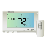
NOTE: Wires marked with
the dotted line are optional.
For your Remote Control to
operate you must connect
the C wire.
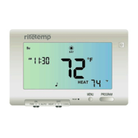
NOTE: Wires marked with the dotted
line are optional. For your Remote
Control to operate you must
connect the C wire

 Loading...