5 Commissioning
Rittal air/water heat exchanger assembly instructions 13
EN
5 Commissioning
Once all the assembly and installation work is
complete, switch on the power supply to the
air/water heat exchanger.
The air/water heat exchanger starts running:
– with Basic controller: The enclosure internal
temperature is displayed.
– with e-Comfort controller: The software version
of the controller first appears for approx. 2 sec.,
then the enclosure internal temperature appears in
the 7-segment display.
You can now make your individual settings on the
unit, e.g. set the temperature or (with e-Comfort
controller only) assign the network identifier, etc.
(refer to the chapter “6 Operation”, page 13).
6Operation
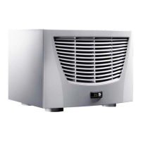
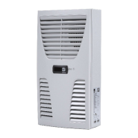
You can operate the air/water heat exchanger using
the controller on the front of the unit (fig. 1, no. 2,
page 4).
6.1 Control using the Basic controller
For unit types 3363.1XX to 3375.1XX.
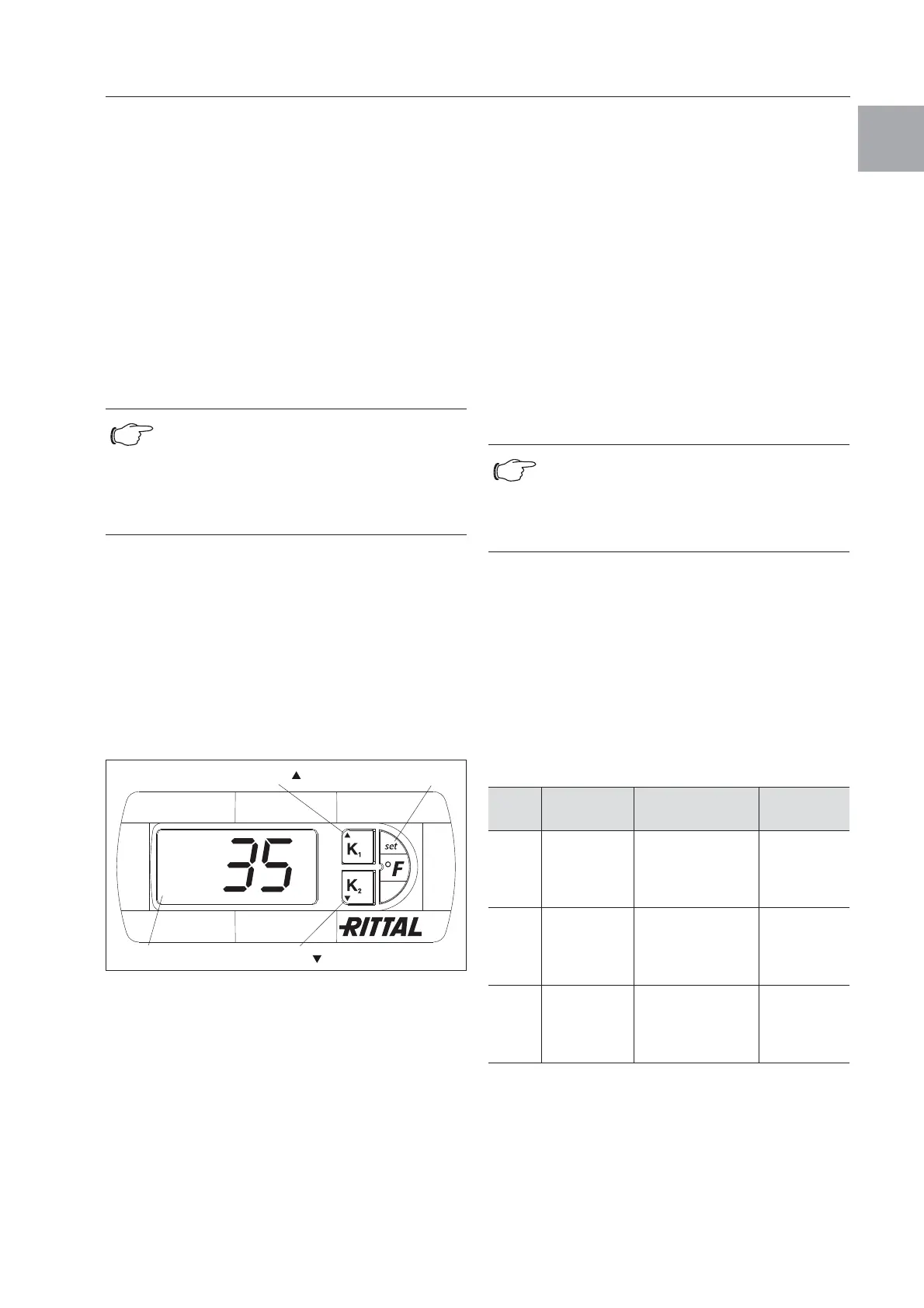
6.1.1 Display and system analysis
Fig. 19:
Display and system analysis of the Basic controller
6.1.2 Properties
The air/water heat exchanger operates automati-
cally, i.e. after switching on the power supply, the
fan (see fig. 2, page 4) will run continuously and
permanently circulate the internal enclosure air.
The magnetic valve controls the cooling water flow
as specified by the temperature setpoint.
The built-in Basic controller ensures automatic
normal shut-down operation of the air/water heat
exchanger by the value of the fixed preset switching
difference of 5 K.
6.1.3 General programming information
Using buttons H2, H3 and H4 (fig. 19) you can
change 3 parameters within the preset ranges
(min. value, max. value). Tables 6 and 7 on page 14
show the parameters which can be altered.
6.1.4 Operation of the Basic controller
The display terminal “H1” consists of a 3-position
7-segment display which indicates the temperature
in °C as well as any system messages. The current
enclosure internal temperature is usually displayed
permanently. In the event of a system message, this
will alternate with the internal temperature display.
6.1.5 Setting the temperature
The setting of the enclosure internal temperature is
preset at the factory to 35°C. To change the value
press key H2 (▲ K
1
) or H3 (▼ K
2
) for one second un-
til °1 appears in the display, then confirm with the H4
“set” key.
The set value can then be altered within the preset
parameters (+20°C to +55°C) via the keys H2
(▲ K
1
) or H3 (▼ K
2
). Press the H4 “set” key for
5 seconds to save the new value. The current enclo-
sure internal temperature is displayed again.
Tab. 5: Warning messages on the display
Note on limiting the volumetric flow
From a volumetric flow of > 400 l/h, no
significant increase in cooling output is
achieved. Appropriate measures must be
taken to regulate the flow rate, e.g. balanc-
ing valves (Model No. 3301.930/.940).
H2 = Key K
1
H4 = Key set/°F
H1 = Display terminal H3 = Key
K
2
Note:
With the Basic controller, the temperature is
preset at the factory to +35°C. In order to
save energy, do not set the temperature
lower than that actually necessary.
Alarm
no.
System
message
Cause Remedy
HI Internal
temperature
of enclosure
too high
Cooling capacity
inadequate/
unit undersized/
unit defective
Check
cooling
capacity/
check unit
LO Internal
temperature
of enclosure
too low
Ambient tempera-
ture too low/
no heat loss in
the enclosure
Check unit
E0 Temperature
sensor faulty
Malfunction, sepa-
ration or tempera-
ture sensor failure
Check
sensor cable
and replace
if necessary
 Loading...