22 Rittal air/water heat exchanger assembly instructions
6 Operation
EN
On the master air/water heat exchanger
(00 = factory setting), set the number of slave units
present in the network:
01: Master with 1 slave air/water heat exchanger
02: Master with 2 slave air/water heat exchangers
03: Master with 3 slave air/water heat exchangers
04: Master with 4 slave air/water heat exchangers
05: Master with 5 slave air/water heat exchangers
06: Master with 6 slave air/water heat exchangers
07: Master with 7 slave air/water heat exchangers
08: Master with 8 slave air/water heat exchangers
09: Master with 9 slave air/water heat exchangers
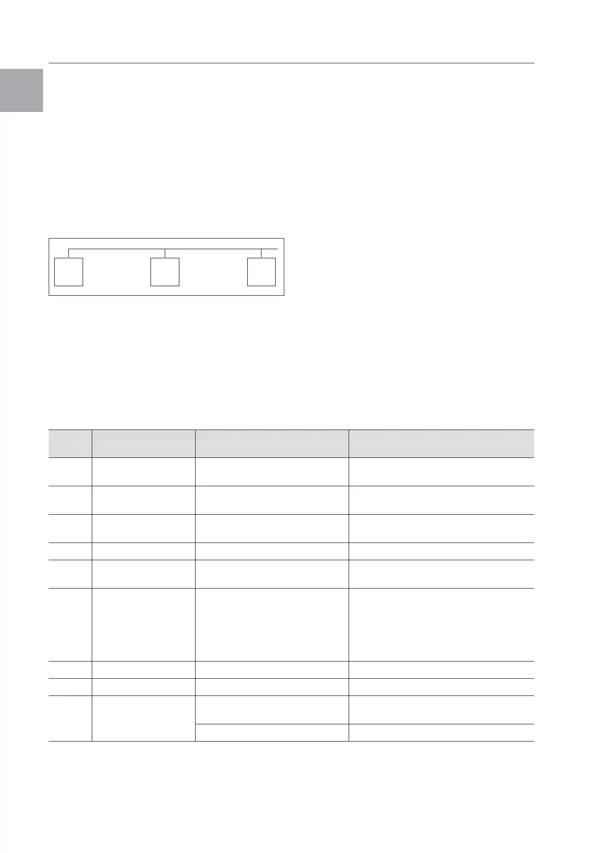
Fig. 26: Master-slave connection (example)
For details of how to set the identifier,
see “6.2.5 Editable parameters”, page 18 or
“6.2.7 Programming overview of e-Comfort
controller”, page 20, parameter “Ad”.
6.2.10 Evaluating system messages
In the e-Comfort controller, system messages are
indicated by a number in the display.
On the slave air/water heat exchanger
(00 = factory setting), set its own address:
11: Slave air/water heat exchanger No. 1
12: Slave air/water heat exchanger No. 2
13: Slave air/water heat exchanger No. 3
14: Slave air/water heat exchanger No. 4
15: Slave air/water heat exchanger No. 5
16: Slave air/water heat exchanger No. 6
17: Slave air/water heat exchanger No. 7
18: Slave air/water heat exchanger No. 8
19: Slave air/water heat exchanger No. 9
Tab. 10: Troubleshooting with the e-Comfort controller
Master
02
Slave
11
Slave
12
Display
screen
System message Possible cause Measures to rectify the fault
A01 Enclosure door open
Door open or door limit switch
incorrectly positioned
Close door, position door limit switch
correctly, check connection if necessary
A02
Internal temperature
of enclosure too high
Cooling capacity inadequate/
unit undersized
Check cooling capacity
A08 Condensate warning
Condensate discharge kinked
or blocked
Check condensate drainage;
correct any kinks or blockages in the hose
A10 Fan Blocked or defective Clear the blockage; replace if necessary
A16
Internal temperature
sensor
Open or short-circuit Replace
A18 EPROM error New board installed incorrectly
Software update needed (only following
board installation with more recent soft-
ware): Enter the programming level with
Code 22; press button 1 and confirm with
“set” until “Acc” appears. Next, disconnect
the unit from the mains and reconnect.
A19 LAN/Master-Slave Master and slave not connected Check setting and cable
A20 Voltage drop Error display not shown Event is stored in the log file
E0 Display message
Connection problem between the
display and the controller board
Reset: Switch power supply off, then switch
on again after approx. 2 sec.
Cable defective; connection loose Replace the boards
 Loading...