6 Operation
Rittal air/water heat exchanger assembly instructions 19
EN
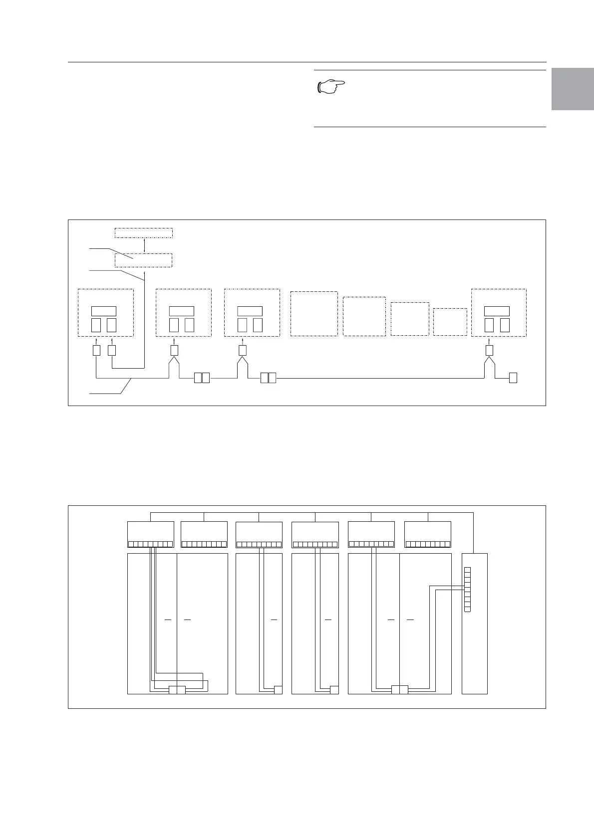
6.2.6 Bus connection
(only when interconnecting several units
with an e-Comfort controller)
When using several air/water heat exchangers,
the serial unit interface can be used to connect up
to ten air/water heat exchangers with the bus cable
(Model No. 3124.100).
When interconnecting, please note the following:
– De-energise the air/water heat exchangers to
be connected.
– Ensure proper electrical insulation.
– Make sure the cables are not laid in parallel to
power lines.
– Make sure that the lines are short.
Fig. 23: Connection example: Master-slave operation
Key
1 Serial interface
2 Serial interface cable
3 Master-slave bus cable (Model No. 3124.100)
RTT Rittal TopTherm air/water heat exchanger
X1 Supply connection/Door limit switch/Alarms
X2 Master-slave connection Sub-D, 9-pole
X3 Serial interface Sub-D, 9-pole
St. Sub-D connector, 9-pole
Bu. Sub-D jack, 9-pole
Adr. Address
Fig. 24: Connection example: Door limit switch and master-slave operation
Key
1 Master air/water heat exchanger
2 Slave air/water heat exchanger
3 2-door enclosure with two door limit switches
4 Enclosure with door limit switch
Note:
The electrical signals at the X2 interface are
of an extra-low voltage (not extra-low safety
voltages in accordance with EN 60 335-1).
X2
CMC
RTT
Master
Ad r.: 09
X1
X2
X3
X1
X2
X3
X1
X2
X3
X1
X2
X3
X2
X3
X2
X2
X2
X2
X2
X2
St. St. St.
Bu.
St.
Bu.
X2
Ad r.: 11 Ad r.: 12RTT
Slave
RTT
Slave
Ad r.: 19RTT
Slave
St.
Bu.
St.
Bu.
3
2
1
X10
L1
L2
N
PE
1
23
4
5
1
X10
X10 X10 X10 X10
X2 X2 X2 X2 X2 X2
X2
L1
PE
1
23
4
5
L1
L2
N
PE
1
23
4
5
L2 L3
L1
PE
1
23
4
5
L2 L3
L1
PE
1
23
4
5
L2 L3
L1
PE
1
23
4
5
L2 L3
L1
L2
N
PE
1
23
4
5
X10
2
3
4
56
1
Adr.: 06 Adr.: 11 Adr.: 12 Adr.: 13 Adr.: 14 Adr.: 15
22 2 2 2
34432
Adr.: 16
 Loading...