6 Operation
Rittal air/water heat exchanger assembly instructions 21
EN
6.2.8 Defining system messages for evaluation
System messages are shown on the display screen
of the e-Comfort controller via the displays A01 to
A20 and E0.
A more detailed explanation of the system messages
may be found in section “6.2.10 Evaluating system
messages”, page 22. See also fig. 25 on page 20.
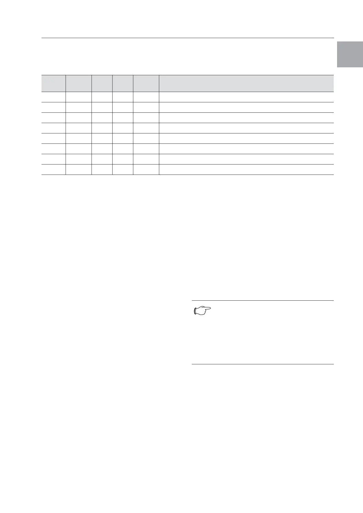
Tab. 9: System messages which may be evaluated via relays
The system messages A01 – A20 may additionally
be evaluated via two floating system message
relays. In this way, one of the two system message
relays may be allocated to each system message.
System message relays with normally open contact,
see wiring diagrams at section “4.6.5 Installing the
power supply”, page 11:
– Terminal 3: NO (normally open, relay 2)
– Terminal 4: Connection of the supply voltage to the
system message relay
– Terminal 5: NO (normally open, relay 1)
The definition NO refers to the de-energised state.
As soon as power is applied to the air/water heat
exchanger, both system message relays (relay 1
and 2) energise.
This is the normal operating state of the air/water
heat exchanger.
As soon as a system message occurs or the power
supply is interrupted, the corresponding relay will
drop out and open the contact.
Program system messages with the value
0: System message is not sent to the system
message relays, but merely appears in the
display
1: System message is evaluated by relay 1
2: System message is evaluated by relay 2
3: System message is neither sent to the system
message relay, nor does it appear in the display
(setting can only be made using RiDiag soft-
ware)
6.2.9 Setting the master-slave identifier
When several air/water heat exchangers are con-
nected together (maximum 10), one of the air/water
heat exchangers must be defined as the “master”
and the others as “slaves”. For this purpose, assign
a corresponding identifier (address) to each air/
water heat exchanger which will enable the air/water
heat exchanger to be identified in the network.
If one of the slave units reaches the set temperature
or if the door limit switch function is activated, the
affected slave unit will report to the master unit,
which then deactivates all the other air/water heat
exchangers.
Progr.
level
Display
screen
Min.
value
Max.
value
Factory
setting
Type or location of fault
7 A01 0 2 0 Enclosure door open
8 A02 0 2 0 Internal temperature of enclosure too high
9 A08 0 2 1 Condensate warning
10 A10 0 2 1 Fan blocked or defective
11 A16 0 2 1 Internal temperature sensor
12 A18 0 2 1 EPROM
13 A19 0 2 0 LAN/Master-Slave
14 A20 0 2 0 Voltage drop
Notes:
– Only one unit may be configured as
master, and its identifier must match
the number of connected slave units.
– The slave units must have different
identifiers.
– The identifiers must be numbered in
ascending order without any gaps.
 Loading...