4 Assembly and connection
RITTAL outdoor cooling unit assembly and operating instructions 31
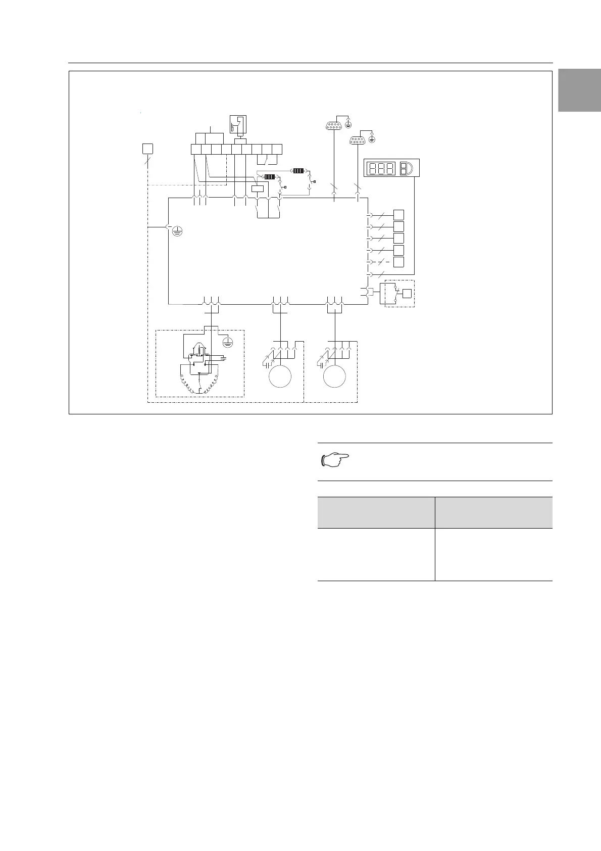
Fig. 7: Electrical wiring plan no. 2
Key
A1 Power PCB
A2 Display terminal
B1 Internal temperature sensor
B2 Icing hazard temperature sensor
B3 Condenser temperature sensor
B4 Ambient temperature sensor
B5 Condensate warning sensor (optional)
C1 Running capacitor
C2 Running capacitor
C4 Running capacitor
E1 Heater 1
E2 Heater 2
F2 Pressostat
F3 Bimetal contact compressor
K3 Alarm relay
Kx Relay K1 heater
Kx Relay K2 alarm 230 V AC
M1 Compressor
M2 Condenser fan (external fan)
M4 Evaporator fan (internal fan)
S1 Door limit switch
(without door limit switch: terminal 1, 2 open)
TB1 Temperature limiter 1
TB1 Temperature limiter 2
X1 Main terminal strip
X2 Master-slave connection
X3 Optional interface
Tab. 1: Contact data
22 21
X1
A1
L1
L2
N
PE
1
23
4
5
11
12 14
38
E2
E1
TB
TB
S1
Mains
L
123
12
3
21
N
PE
PE
6
Power
S1 K2
K3
A2
A1
K3
K1
MS1 Serial
X2
X3
A2
Kx
M2
1
2
3
M1
C1
1
2
3
M4
1
2
3
2
1
F2
14
12 13
10 11
C
F2
B1
B2
B3
B4
B5
P
NTC_I
NTC_E
NTC_C
NTC_A
Level
Te rm
C2
C1
C4
M2M1 M4
1~
MM
1~
CS 9768.152
2
2
2
2
2
4
Note:
For technical data refer to the rating plate.
AC
cos f = 1
DC
L/R = 20 ms
I max. = 2 A
U max. = 250 V
I min. = 100 mA
U max. = 200 V
U min. = 18 V
I max. = 2 A
 Loading...