30 RITTAL outdoor cooling unit assembly and operating instructions
4 Assembly and connection
4.5 Performing the electrical installation
4.5.1 Bus connection
(only in conjunction with several units
with a Comfort controller)
When using several cooling units, the serial device
interface X2 can be used to connect up to ten cool-
ing units with the bus cable (Model No. SK 3124.100).
When interconnecting, please note the following:
– De-energise the cooling units to be connected.
– Ensure proper electrical insulation.
– Make sure the cables are not laid in parallel to
power lines.
– Make sure that the lines are short.
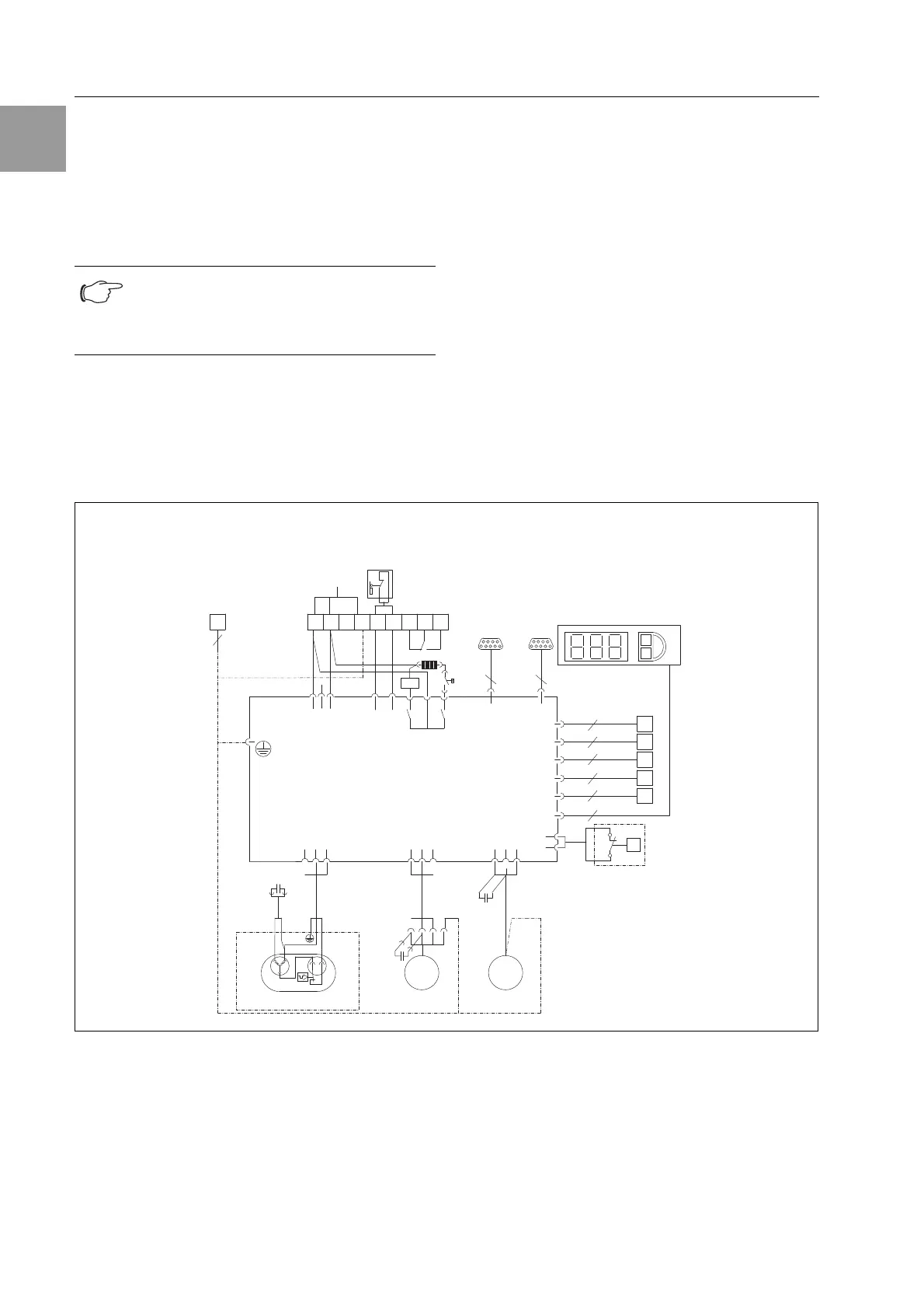
4.5.2 Installing the power supply
– Power supply is via the 9-pole female connector.
Complete the electrical installation by following the
wiring plan (see Fig. 6 and 7).
– If you would like the system messages from the
cooling unit to be evaluated via the system mes-
sage relay, you should also connect a suitable
low-voltage cable to connection clamps 3 – 5.
Fig. 6: Electrical wiring plan no. 1
Note:
The electrical signals at the X2 interface are
of an extra-low voltage (not extra-low safety
voltages in accordance with EN 60 335-1).
22 21
X1
A1
L1
L2
N
PE
1
23
4
5
11
12 14
38
Hz
TB
S1
Mains
L
123
12
3
21
N
PE
PE
6
Power
S1 K2
K3
K3
K1
MS1 Serial
X2 X3
A2
Kx
M2
1
2
3
M1
M1
1
2
3
M4
1
2
3
2
1
F2
F3
C
S
R
F2
B1
B2
B3
B4
B5
P
NTC_I
NTC_E
NTC_C
NTC_A
Level
Te rm
C2
C1
C4
M2 M4
1~
MM
1~
CS 9761.212, CS 9762.212
2
2
2
2
2
4