This identification is transferred once, as soon as the fault with the number XXXX/BCD has been
rectified. This information can be used to delete the fault messae in the PLC.
Evaluation of the interface signals in the PLC:
Messages:
If bit 1 and bit 3 of the input byte have a 1 signal, the transmitted information is a system messae. In
this case, the meaning of bit 0 is either the information "store fault message" (bit 0=0) or "cancel fault
message" (bit 0=1).
Bit 4 to 7 represent the appropriate message number (BCD).
Temperature:
If the AND operation of bit 1 and bit 3 is not fulfilled, the input information represents the actual
internal temperature of the enclosure. In this case, both BCD digits have valid values (<=9).
b) Parallel fault codes (Level 8="1").
This can be accessed as follows:
Every one of the the eight outputs stands for a certain system message (see below). It is not
possible to display the internal temperature at the same time as the system messages.
Output/Bit System Message
0 Max. enclosure internal temperature
1 Filter mat soiled
2 Enclosure door is open
3 High-pressure monitor
4 Evaporator
5 Current monitor, compressor
6 Current monitor, internal fan
7 Current monitor, external fan
Because these fault codes are transmitted through an optocoupler, they can be switched to a parallel
transmission.
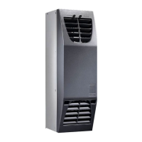
6. Technical Information
The cooling unit (compression refrigeration unit) consists of four main components: the coolant
compressor, evaporator, condenser, and the control or expansion valve, which are connected by
suitable pipework. This circuit is filled with a readily boiling substance, the coolant. The R134 a
(CH
2
FC
3
) coolant is free from chlorine. It has an ozone destroying potential (ODP) of 0 and is
therefore environmentally friendly. A filter dryer which is integrated in the hermetically sealed cooling
circuit, provides effective protection against moisture, acid, dirt particles, and foreign bodies within
the cooling circuit.