5.2.3.3 Door Limit Switch S 2 (supplied by customer)
Where a door limit switch is used and the enclosure door is open (contact is closed when door is
open), the cooling unit (fans and condenser) will switch off after approx. 10 s, thereby avoiding an
increase in condensation while the door is open. To avoid cyclic operation, switch-on of the
condenser and external fan is delayed by about 3 minutes after the door has been closed. The
internal fan will start up immediately on closure of the door. Connection is made at the terminal strip
X10, terminals 1 and 2. The extra low voltage is supplied by the internal power pack, current is
approx. 30 mA DC (no extra low safety voltage). Connect the door limit switch free from potential
only, no external voltage! The display will flash during the door delay time. The system message
"1010" is transmitted via the PLC interface.
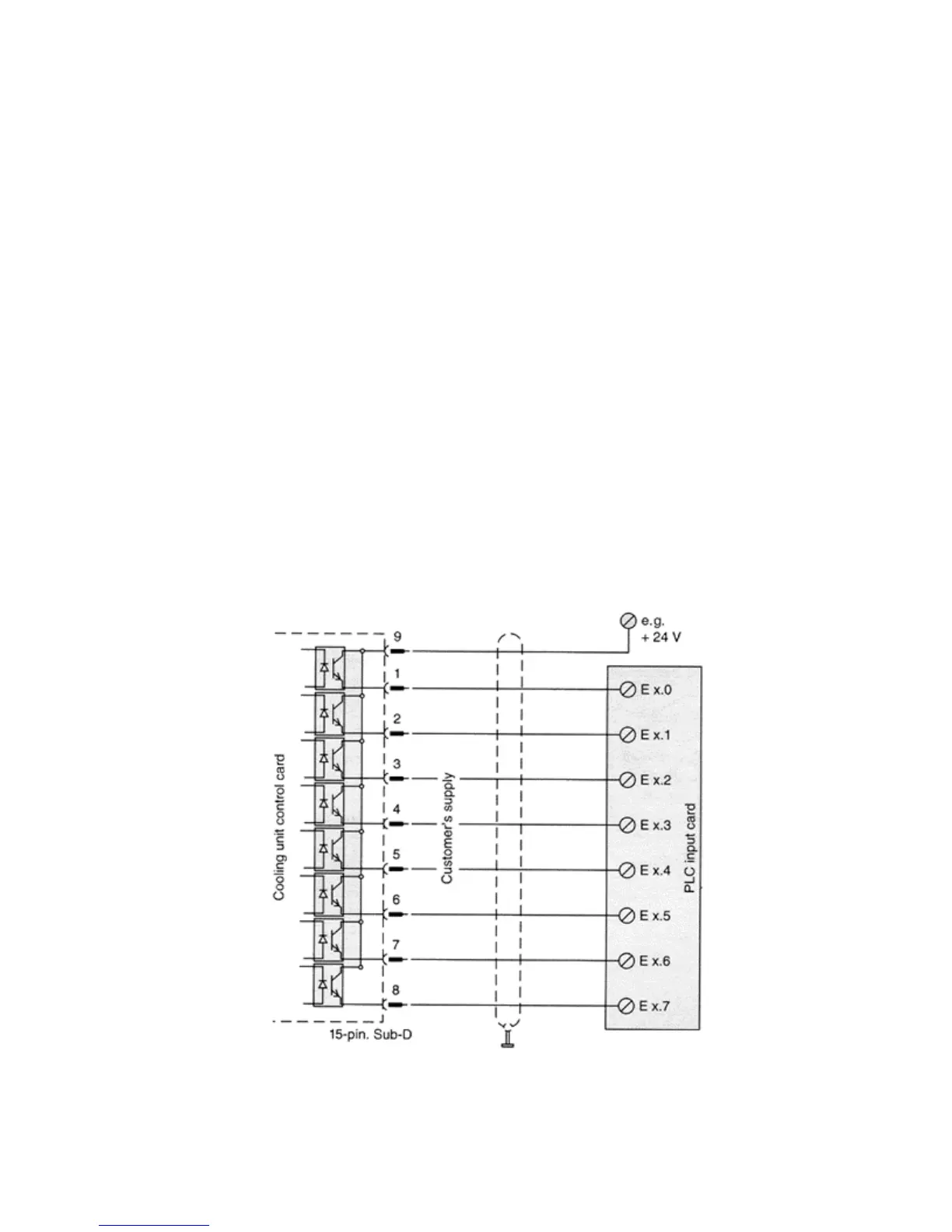
5.2.3.4 PLC Interface X2 (Option)
The interface is used for the transmission of the actual internal temperature of the enclosure an any
system messages of the cooling unit to the PLC. The transmitted information can be displayed by
means of the output facilities (e.g. plain text display) which are connected to the PLC, or by means of
the serial interface to a higher order computer.
Construction of the PLC interface:
The construction is potential separated via optocoupler (wiring diagram fig. 5.4). Connection is
made by the customer to the 15-pin socket on the control board (fig. 5.4) to the PLC input card.
Figure 5.4 PLC Interface